background image

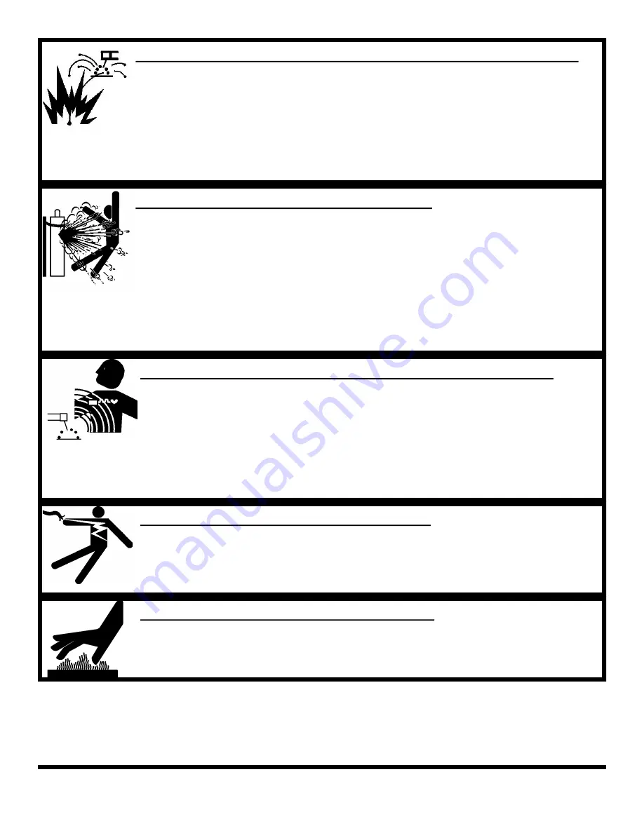
WELDING SPARKS CAN CAUSE INJURY, FIRE, OR EXPLOSION 

 

Remove all flammable materials from the welding area 

 

Always have a charged fire extinguisher available in the welding area 

 

When not welding make sure the welding tip is not grounded, this causes a heat build up and       
possible fire 

 

Avoid welding  near hydraulic lines, fuel lines, electrical cords, air hoses, or welding guns and    
cables 

 

Sparks and hot metal fly out from the work area when welding, wear approved safety glasses with 
side shields under approved helmets, wear proper body and hand protection, and wear flame        
resistant ear plugs to keep sparks from entering the ears 

CYLINDERS CAN EXPLODE IF DAMAGED 

 

Gas cylinders contain gas under very high pressure. If damaged they can result in that cylinder ex-
ploding. Gas cylinders are a major part of metalworking and must be treated with care. 

 

Protect gas cylinders from excessive heat, mechanical shocks, slag, open flames, sparks, and arcs 

 

Always keep cylinders in an upright position securely fastened to a fixed support 

 

Valve protection caps should always be in place and hand tight except when the cylinder is in use 

 

Keep all cylinders away from any welding or electrical circuits 

 

Never allow the arc from a welder to contact a cylinder 

 

Never cut any type of pressurized cylinder, an explosion could result 

 

Always turn your face away from the valve when opening the cylinder 

 

Read and follow all instructions on compressed gas cylinders, associated equipment, and CGA pub-
lication P-1 listed in the Safety Standards before using 

ELECTRIC AND MAGNETIC FIELDS MAY BE DANGEROUS 

 

Electric current used in arc welding can create Electro-Magnetic Fields (EMF) 

 

Magnetic fields can affect pacemakers and wearers should avoid proximity to EMF. Wearers need  
to contact their doctors before operating this type of equipment 

 

Exposure to EMF during operation of this equipment may have other health effects which are not 
yet known 

 

Route the work and torch cables together and not around your body 

 

Do not place your body between the torch cable and the ground cable. They both need to be on the 
same side of your body when operating 

 

Do not work next to the welding machine 

ELECTRICALLY POWERED EQUIPMENT 

 

Disconnect power source or turn off circuit breaker at the power panel before working on any   
equipment 

 

Only install equipment using the US National Electrical Code, all local codes, and the manufactur-
er’s recommendations 

KDAR Company 

HOT PARTS CAN CAUSE SERIOUS BURNS 

 

Do not touch hot parts without wearing protection. 

 

Allow the torch to cool sufficiently before working with parts that could potentially be hot. 

Summary of Contents for 250WFG

Page 1: ...ding ALL of this manual and the safety precautions and warnings illustrated in this manual KDAR Company Tel 314 692 8555 1 Mulch Lane Fax 314 692 8578 St Louis MO 63044 Web Site www hotmaxtorches com...

Page 2: ...r helmet or shield when operating ANSI Z49 1 approved shade 9 recommended for all cutting currents less than 300 amperes The lens should conform to ANSI Z87 1 standards for testing Wear approved safet...

Page 3: ...from a welder to contact a cylinder Never cut any type of pressurized cylinder an explosion could result Always turn your face away from the valve when opening the cylinder Read and follow all instruc...

Page 4: ...California Health and Safety Code Section 25249 5 et seq PRINCIPAL SAFETY STANDARDS AMERICAN WELDING SOCIETY AWS C5 2 Recommended Practices for Plasma Arc Cutting AWS F4 1 Recommended Safe Practices...

Page 5: ...collets one short cap and one long cap Arc Welding 300 Amp electrode holder with 10 cable assembly Common Features 300 Amp ground clamp with 10 cable assembly Tank tray that holds up to 9 5 diameter...

Page 6: ...2 Tank Deck 1 6mm Lock Washers 6 Gas Hose 5 1 TIG Collet Body 1 10 Solid Wheels 2 Ground Clamp w 10 Cable 1 TIG Collets 3 Axle 1 Long Black Cap 1 TIG Foot Peddle w 15 Lead 1 Caster Retention Nuts att...

Page 7: ...and Controls 1 Output Voltage Adjust Knob MIG 2 Amps For MIG Arc Welding 3 Wire Feed Speed for MIG Welding 4 Welding Method Indicator 5 MIG Spool Gun Selector 6 Welding Method Selector 7 MIG Gun Port...

Page 8: ...ding 1 Insert the male connector on the electrode holder cable into the positive quick connect port 1 Figure 6 2 Insert the male connector on the ground clamp cable into the negative quick connect por...

Page 9: ...75 80 Argon and 20 25 CO2 For TIG welding pure Argon must be used 1 Insure the cylinder is properly secured to the welder a wall or other stationary support to prevent it from falling over during setu...

Page 10: ...em Keep your head away from the fumes Arc Rays Can Burn Skin and Eyes Always were eye ear and body protection Cutting Sparks Can Cause Injury Fire or Explosion Do not use near flammable material Do no...

Page 11: ...e feed speed 3 Power Level Dial 3 Figure 13 Sets the power level from 50 250 Amps Power level can be ad justed while welding 4 Welding Method Selector Switch 4 Figure 13 Set rocker switch to the cente...

Page 12: ...Flip down the left and right idle arms and flip up the wire tensioning arm 5 Turn the welder on press the Quick Feed Button to advance the wire quickly through the gun hose Note If feeding problem oc...

Page 13: ...e wheels have the size identification required on the outside Note The wire will run through the grooves on the outside of the drive roller 7 Re attach the drive roller retention covers 3 by turning t...

Page 14: ...y clean the inside of the tube 3 The motor and gearbox needs no lubrication or maintenance Gun Cable 1 To clean the cable liner remove the gun cable assembly from the welder and lay it out straight on...

Page 15: ...tput Possible Cause 1 Check to insure the power switch is turned on 2 Insure correct voltage is applied to the welder and the plug is correctly wired 3 Check to insure the circuit breaker is not tripp...

Page 16: ...ary 4 Insure proper gas flow for the process 5 Make sure the connections for the ground cable are correct 6 Make sure the drive roll is installed and aligned properly 7 Make sure the wire size is corr...

Page 17: ...ator Flow Meter 250WFG Replacement Contact Tips Model 23247 025 Contact Tip Model 23248 030 Contact Tip Model 23249 035 Contact Tip Model 23250 040 Contact Tip Model 23251 045 Contact Tip Model 23246...

Page 18: ...TIG Gun Model 23240 250WFG Replacement TIG Foot Pedal Model 23245 250WFG Replacement Electrode Holder Model 23258 250WFG Replacement Ground Clamp Model 23201 Replacement Standard Regulator for Argon...

Page 19: ...work is required DO NOT RE TURN THIS WELDER TO THE RETAIL ER Contact KDAR Company for instruc tions Visit www hotmaxtorches com or call KDAR Company M F 8AM 5PM CST to lo cate the nearest Authorized S...

Page 20: ...KDAR Company 1 Mulch Lane St Louis MO 63044 Phone 314 692 8555 Fax 314 692 8578 Rev 2 Nov 2013...

Reviews: