TRANSLATION OF THE ORIGINAL OPERATING INSTRUCTIONSREAD CAREFULLY PRIOR TO STARTING UP! KEEP OPERATING INSTRUCTIONS IN A SAFE PLACE! ART.:ISSUE:
OPERATING INSTRUCTIONS
0207
06/2016
8080
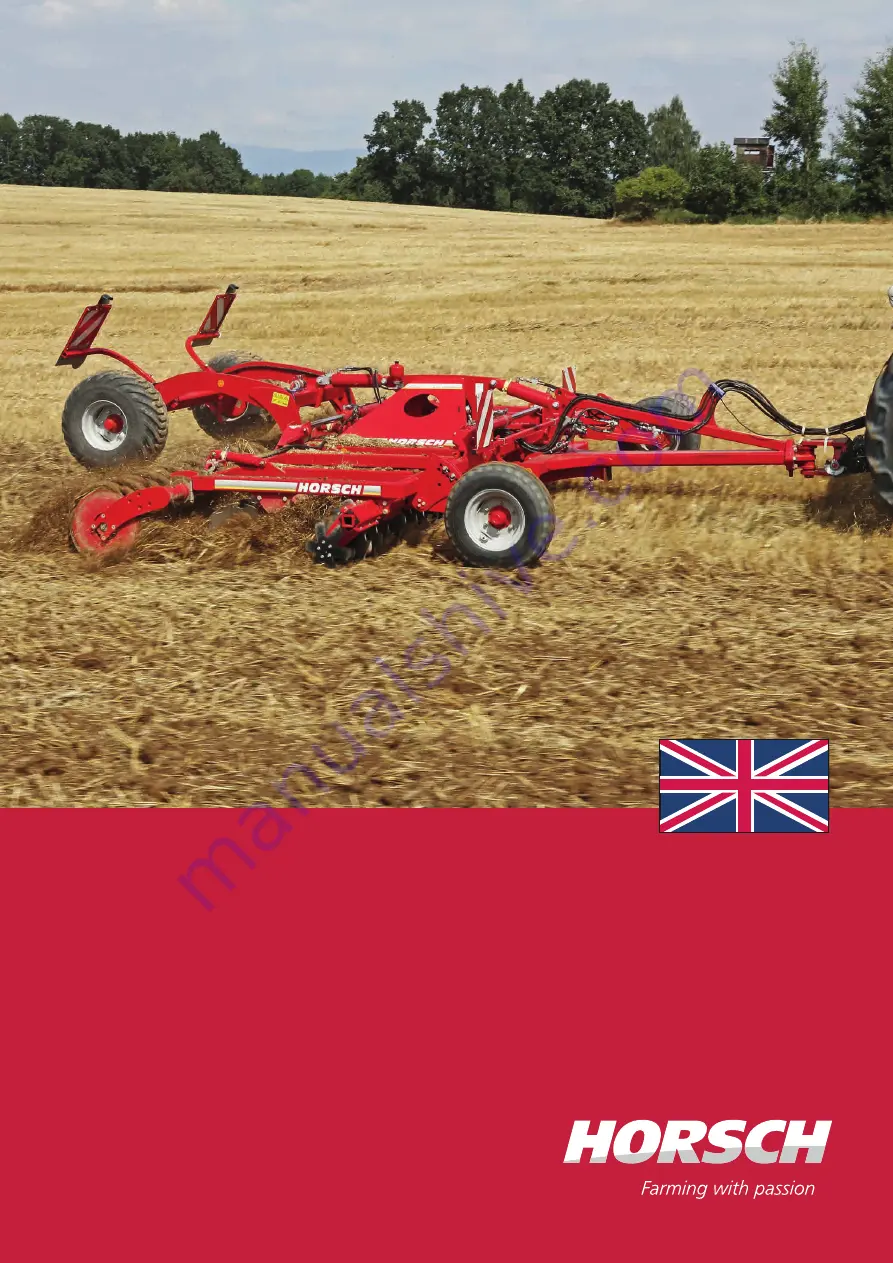
Joker 5/6/8 RT Classic
Page 1: ...RANSLATION OF THE ORIGINAL OPERATING INSTRUCTIONS READ CAREFULLY PRIOR TO STARTING UP KEEP OPERATING INSTRUCTIONS IN A SAFE PLACE ART ISSUE OPERATING INSTRUCTIONS 0207 06 2016 8080 Joker 5 6 8 RT Classic ...
Page 2: ... refers to conforms with all relevant fundamental health and safety requirements of the EC directive 2006 42 EC For proper implementation of the heath and safety requirements mentioned in the EC directive the following standards and technical specifications have been used DIN EN ISO 4254 1 2013 10 DIN EN ISO 12100 2011 03 Schwandorf 06 06 2016 Documentation Representative Place and date Manfred Kö...
Page 3: ... and spare parts list for the machine speci fied above I have been instructed by an authorized dealer or a Service Engineer from HORSCH in the opera tion and functions as well as the safety related requirements of the machine I am aware that the right to claim warranty will only be effective if this form is returned to the responsible dealer or handed over to the Service Engineer properly complete...
Page 4: ......
Page 5: ...of construction Initial installation Fittings Publication date of Operation Manual Latest change Address of Retailer Name Road Town City Tel Customer No Retailer Address of HORSCH HORSCH Maschinen GmbH 92421 Schwandorf Sitzenhof 1 92401 Schwandorf Postbox 1038 Tel 49 0 9431 7143 0 Fax 49 0 9431 41364 E mail info horsch com Customer No HORSCH en 02 10 2019 06 2016 Joker 5 6 8 RT Classic 8080 07 ...
Page 6: ... Type plate 19 Design 21 Overview 21 Hydraulics 22 Lighting 24 Coulter discs 25 Packer 25 Tyre Packers 26 SteelDisc Packer 26 RollFlex Packer 26 FarmFlex Packer 26 Aluminium clips 27 Instruction stickers 28 Operation 29 Commissioning Tractor change 29 Adapting the drawbar 29 Connecting and transport position 29 Parking 31 Folding 32 Unfolding 32 Folding 32 Depth setting 33 Use in the field 35 Soft...
Page 7: ...3 ...
Page 8: ...ss the acknowledgement of receipt to the sales partner This confirms your formal acceptance receipt of the machine The warranty period starts with the date of delivery We reserve the right to alter illustrations as well as technical data and weights contained in these operating instructions for the purpose of improv ing the machine The illustrations in these operating instructions show different v...
Page 9: ... claim forms must be submitted to HORSCH through your local HORSCH sales partner Consequential damage The machine has been manufactured by HORSCH with greatest care However despite the intended use deviations in placing quantity up to total failure may be caused by e g damage caused by external influences wear of wear items missing or damaged cultivation tools incorrect travel speeds incorrect set...
Page 10: ...ed serviced and repaired by persons who are familiar with it and have been made aware of the dangers involved see Qualification of personnel Spare parts Genuine spare parts and accessories from HORSCH have been specially designed for this machine Spare parts and accessories which are not deliv eredbyus havenotbeentestedorapprovedbyus Installation or use of non original HORSCH products may have a d...
Page 11: ...rating instructions accessible for the machine operator ensure that the operator has read and under stood the operating instructions Groups of operators Persons who work with the machine must have been trained for the different activities involved Instructed operators These persons must have been trained for their respective activities by the owner or other quali fied experts This refers to the fo...
Page 12: ...e loaded with at least 20 of the tractor weight For road transport the machine must be set to transport position The machine must have been folded up and secured see chapter Folding and Hitching up and transport position Clean soil from the folding areas before fold ing up Otherwise there could be damage to the mechanics If present Secure the hydraulic cylinders on undercarriage and drawbar in tra...
Page 13: ...l physical injuries The following machine parts are particularly important for safety Hydraulics Brakes if available Connecting features Protective features Lighting If in doubt about the safety relevant status of the machine e g in case of leaking out operating fluids visible damage or unexpected changes in travel behaviour Immediatelyshutdownandsecurethemachine If possible locate and rectify the...
Page 14: ...e equipped with pressure accumulators Do not open or work welding drilling on pressure accumulators Even when empty the tanks are still preloaded by gas pressure The hydraulic system must be depressurized before maintenance Brake system Depending on the equipment the machines can be equipped with a pneumatically or hydrauli cally operated service brake system For road travel the brake system must ...
Page 15: ...The following technical limiting values are of particular importance for safety permissible total weight maximum axle loads maximum drawbar load top speed See chapter Technical data type plate and type approval Also pay attention to the max permitted loads for the tractor Use in the field DANGER No passengers are allowed to ride on the machine Checktheareaimmediatelyaroundthemachine forchildren be...
Page 16: ...adverse ly affect the functionality and the operational safety of the machine This can lead to severe or even fatal physical injuries Do not make any structural changes or ex tensions to the machine that have not been approved by HORSCH Structural changes and extensions must only be made in an authorized workshop or by an operator who has been trained by HORSCH Comply with country specific instruc...
Page 17: ...l openings which should stay clear of water steam or cleaning agents for reasons of safety or operation Do not aim the water jet directly on electric or electronic components and bearings When cleaning with high pressure or steam cleaning equipment keep a distance of at least 50 cm to machine components After cleaning check all hydraulic lines for leaks and loose connections Check for chafing and ...
Page 18: ...lically raised machine parts can lower slowly and unnoticed Failing to pay attention to the danger zone can result in severe or even fatal physical injuries Do not stand under lifted loads Lower such loads to the ground first Instruct persons to leave the danger zone around the machine and tractor Before working in the danger zone of the ma chine or between machine and tractor Shut down the tracto...
Page 19: ...uld read and fol low the operating instructions 00380055 Watch out for fluids spraying out under high pressure fol low the notes in the operating instructions 00380133 Never reach into areas where there is a risk of crushing as long as parts could still be moving 00380134 Stay clear of swinging area of foldable machine parts 00380135 The pressure accumulator is charged with gas or oil pres sure Di...
Page 20: ...permitted if the safety support is in place 00380953 Loading hook hook the slinging gear chains ropes etc into this loading hook during loading Position of safety stickers 00380252 00380134 00380135 00380299 00380134 00380135 00380896 00380953 00380134 00380135 00380896 00380299 00380134 00380135 00380054 00380055 00380133 00380294 16 ...
Page 21: ...r low loader The permissible dimensions and weights for transport must be complied with The tractor must be big enough so that suffi cient steering and braking abilities are ensured If the machine is hitched up in two point mode the tractor link arms must be blocked against swinging sideways On a trailer or low loader the machine must be secured with tensioning straps or other means Attach lifting...
Page 22: ...75 180 240 175 235 240 320 Design related top speed road transport Specification in type approval Implement attachment tractor link arm Cat III III IV IV Implement attachment adjustable drawbar Ø Drawbar eye ball and socket joint mm 42 51 42 51 42 51 71 NOTE Deviations due to technical further development reserved The weight of the attached implement depends on the equipment data with minimum equi...
Page 23: ...te The type plate with the CE mark is located on the frame of the machine Data on the type plate Serial number Permissible total weight Drawbar load DL Axle load Machine type Year of construction 0 1 2 3 0 4 19 ...
Page 24: ...95 2390 2830 2590 2998 3000 6000 2850 3320 6000 3080 2998 2390 3122 2368 2370 3120 6000 3320 6000 3080 2998 2390 3122 2368 2390 3080 3350 3000 4140 2910 6010 3884 2390 3127 2375 2375 6000 3130 4140 2910 6010 3884 2390 3127 2375 2390 3000 3840 4140 20 ...
Page 25: ...heel 4 Spade disc 5 Side limitation 6 DiscSystem 7 Packer here FarmFlex Packer 8 Hydraulic cylinder Packer 9 Undercarriage 10 Lighting 11 Hydraulic cylinder undercarriage 12 Hydraulic cylinder for wings 13 Hydraulic cylinder for drawbar 2 3 4 5 7 9 10 1 6 8 11 12 13 21 ...
Page 26: ... plug in all hydraulic lines Otherwise components may get damaged because of interrelated functions Observe the notes on hydraulics and pressure accumulator in chapter Safety and responsibility 2 3 4 5 6 1 Lift lower packer and drawbar 1 Tractor control unit 2 Tractor hydraulic coupling 3 Lock valve 4 Six way valve 5 Hydraulic cylinder for drawbar 6 Hydraulic cylinder Packer The right for changes ...
Page 27: ...oupling 3 Double acting lock valve 4 Hydraulic cylinder for wings 5 Pressure gauge 6 Throttle Ø 0 6 mm 7 One way restrictor 8 Single acting lock valve 9 Pressure accumulator The right for changes in design distributor couplings lines etc remains reserved Identification of hydraulic hoses The symbol is located above the hose that re quires pressure to bring the machine in transport position lift ou...
Page 28: ...amp direction indicator Plugs and cable assignment No Desig Colour Function 1 L yellow Indicator left 2 54 g 3 31 white Earth 4 R green Indicator right 5 58 R brown Rear light right 6 54 red Brake light 7 58 L black Rear light left WARNING Traffic accidents caused by defective lighting Check the lighting before setting off Check warning notices and lamps for cleanli ness 24 ...
Page 29: ...h high pressure cleaners Packer In the working position the machine runs on the packer Due to the weight of the machine a high consolidation and a fine crumbly level surface is achieved Packer variants Tyre Packers SteelDisc Packer RollFlex Packer FarmFlex Packer With cohesive soils the packers may become blocked with soil and thus become considerably heavier This may overload machine compo nents ...
Page 30: ...nsolidation on heavy dry soils and a good cut ting effect it is particularly suitable for stony soils RollFlex Packer RollFlex Packer Excellent self cleaning under moist conditions Consolidation in strips with high mixing effect and a very high levelling potential Not recommended for stony or large clot soils FarmFlex Packer FarmFlex Packer Rubber roller with excellent consolidation on medium soil...
Page 31: ...ick ness 7 mm 10 mm 19 mm 30 mm 50 mm NOTE Pay attention to the ratio on the machine see Depth setting WARNING Risk of injury on the hydraulic cylinders Limbs may be pinched by unintentional retrac tion of the piston rods Lock control units mechanically or electrically depending on the version Make sure when placing or removing clips that the control units are not operated by any other person CAUT...
Page 32: ... tyre pressure at regular inter vals adapt if necessary see maintenance overview Observe folding pressure of 70 90 bar 5 6 8 RT 70 90 bar Retighten the wheel nuts wheel bolts after 50 km or 10 hours Retighten every day see maintenance overview Lock valve a field road b depth setting a b Collision of packer elements when clips are inserted Remove aluminium clips before road travel 00380523 28 ...
Page 33: ...ght of the drawbar hitch lower bore 480 550 mm upper bore 550 600 mm Support the drawbar at the front with a height adjustable jack Pull out the bolt on the hydraulic cylinder Correct the height of the drawbar and reinsert the bolt Connecting and transport position DANGER There is a risk that persons may become crushed and severely injured between machine and tractor Instruct persons to leave the ...
Page 34: ...the support and secure at the bottom with the bolt Secure the bolt with a clip pin Support folded Folding the machine see Folding Observe the permissible transport heights Joker 8 RT and ensure ground clearance Remove the wheel chocks and put them in the bracket provided securing WARNING Danger of road accidents caused by losing the machine or machine parts Check all interlocks before starting to ...
Page 35: ...ke and or wheel chocks When unhitching machines with pneumatic brake always disconnect the red connection supply line first WARNING Leaking hydraulic fluid can cause serious in juries Danger of injury by unwanted machine movements Connect and disconnect the hydraulic lines only when the hydraulics have been de pressurized on both machine and equipment sides Lift the machine completely If necessary...
Page 36: ...carriage and drawbar and lift the machine completely Remove the aluminium clips from the hydrau lic cylinders of undercarriage and drawbar Unfold the machine and pre load with 70 to 90 bar Folding Extend undercarriage and drawbar and lift the machine completely Folding the machine Joker 5 6 RT Place aluminium clips on the piston rods of the hydraulic cylinders of un dercarriage and drawbar Place a...
Page 37: ...2 5 cm clips must be placed in addition 1x yellow 1x blue WARNING Risk of injury on the hydraulic cylinders Limbs may be pinched by unintentional retrac tion of the piston rods Lock control units mechanically or electrically depending on the version Make sure when placing or removing clips that the control units are not operated by any other person Set the shut off valve on the drawbar to Depth se...
Page 38: ...d move ment 2 3 1 Lift the sensing wheel before starting to work and pull out the depth guide pin 3 Set the working depth of the machine Lower the sensing wheel to the ground The depth guide pin 3 must be as close as possible at the lower end of the link motion 1 Insert the pin in the first hole possible from the bottom Slightly lift the machine if necessary Check the setting again after travellin...
Page 39: ...iage approximately to the middle Switch the control unit to floating posi tion This results in pressure compensation and the undercarriage moves slightly up Approx 30 50 mm stroke travel shall remain on the piston rod for damping Position of control units during use in the field Position Control unit Floating position Locked position Supply Folding Lift lower undercarriage Tools Tractor link arm H...
Page 40: ...1 3 2 3 1 2 Brake position Optional equipment Brake system The machine can be equipped with a pneu matic or hydraulic brake system The machine is equipped with a parking brake for safe parking DANGER Uncontrolled rolling of the machine can cause severe injuries by crushing or rolling over Park the machine only on level ground with sufficient load bearing capacity Secure the machine with wheel choc...
Page 41: ...caught in any place 3 Releasetheparkingbrake Theropesmustbe relievedandthewheelsmustbefreetorotate 1Hydr Kupplung 2Handlösepumpe Maschine En Dateiname Zeichnung HydraulischeBremse 3Notbremsventil 1 2 3 4 5 4Auslösebetätigung Federstecker 5Druckspeicher 6Bremszylinder 6 6 1 2 3a 4 5 6 3b Hydraulic brake 1 Hydraulic coupling for brake 2 Button of releasing pump 3a Break away brake valve position A 3...
Page 42: ...ting of the machine more difficult Always release the parking brake before transport travels The ropes must be relieved and the wheels must be free to rotate Maintenance Check the function of the parking brake before hitching up the machine Where necessary adjust the cable or the brake shoes Function of the breakaway brake valve The valve has two positions A operating position B emergency braking ...
Page 43: ...tween in case of adjoining passes The height should be set to approx 5 cm above the field The working depth can be matched to the field conditions if this should be necessary Maintenance Regularly lubricate the pivot joint Adjust the height as required Replace the plate if worn 39 ...
Page 44: ...ations lubricantsand mineral oil products present no danger to health You should however avoid longer contact to the skin and not breathe in any fumes Maintenance Periods The maintenance intervals are determined by various different factors Various operating weather and soil conditions as well as working speeds affect the mainte nance intervals but also the quality of the lu bricants and cleaning ...
Page 45: ...essary Check condition and function of all protective features and replace if necessary In use Hydraulics WARNING Lower all hydraulically lifted parts e g wings packer undercarriage etc to the ground before performing any work on the hydraulic system Depressurise the hydraulics on the tractor and implement side Hydraulic system and components Check all hydraulic components and hoses for function l...
Page 46: ... axle journal Check clearance and adjust if necessary may only be performed by a specialist workshop 120 h 6 months Safety installations Lighting and warning boards Check condition and function daily Warning and safety stickers Check that they are in place and legible daily At the end of the season Complete machine Perform care and cleaning work do not spray plastic parts with oil or similar Spray...
Page 47: ...bricate bolt on the drawbar 2 daily Lubricate safety pin 4 40 h Lubricate the side limiter bearings 2 40 h Parking brake 1 100 h Wheel hub support wheel 2 200 h Wheel hub undercarriage brake 200 h NOTES depending on equipment Lubrication grease DIN 51825 KP 2K 40 43 ...
Page 48: ...25 KP 2K 40 Number of lubrication points in brackets Lubricate the lift bearings on the packer shafts 23 daily Tractor link arm 2 daily Lubricate pin on folding cylinder 4 40 h NOTES depending on equipment Lubrication grease DIN 51825 KP 2K 40 44 ...
Page 49: ...he disposal of auxiliary and operating me dia as well as other chemicals you must strictly comply with the specifications in the respective safety data sheets Decommissioning If the machine is no longer suitable for use and needs to be disposed of it must be decommis sioned All machine parts must be separated by material and passed on to environmentally friendly waste disposal or recycling Attenti...
Page 50: ... 0 6 1 8 9 10 4 6 1 00 5 5 6 8 10 4 15 3 17 9 7 1 00 9 3 11 5 17 2 25 30 8 1 25 13 6 16 8 25 37 44 8 1 00 14 5 18 27 40 47 10 1 50 26 6 33 50 73 86 10 1 25 28 35 53 78 91 12 1 75 46 56 86 127 148 12 1 25 50 62 95 139 163 14 2 00 73 90 137 201 235 14 1 50 79 96 150 220 257 16 2 00 113 141 214 314 369 16 1 50 121 150 229 336 393 18 2 50 157 194 306 435 509 18 1 50 178 220 345 491 575 300 20 2 50 222...
Page 51: ...0 31 2 35 2 44 7 50 2 7 16 11 1 33 9 36 6 50 2 55 6 70 5 78 6 1 2 12 7 47 5 54 2 77 3 86 8 108 5 122 0 9 16 14 3 67 8 81 3 108 5 122 0 156 0 176 3 5 8 15 9 95 0 108 5 149 1 169 5 216 0 244 0 3 4 19 1 169 5 189 8 271 1 298 3 380 0 427 0 7 8 22 2 176 3 196 6 433 9 474 5 610 0 678 0 1 25 4 257 6 278 0 650 8 718 6 915 2 1017 1 1 8 28 6 359 3 406 8 813 5 908 4 1302 1458 1 1 4 31 8 508 5 562 7 1139 1261...
Page 52: ... Drawbar eye 18 21 Drawbar load 18 E Environment 45 Environmental protection 12 F FarmFlex Packer 26 folding 32 Folding 32 Foreword 4 H Headland 35 Height 18 Hitching 21 Hose bracket 21 Hydraulic brake 37 Hydraulic cylinders 21 hydraulic hoses 41 Hydraulics 10 18 22 41 Hydraulic system 41 I Installation 17 L Length 18 Liability 4 Lift bearings 44 Lighting 21 24 42 Lock valve 33 Lubrication points ...
Page 53: ...21 Spare parts 6 speed 8 SteelDisc Packer 26 Stickers 15 28 Support 30 31 Support wheel 43 Support wheels 18 T Technical data 18 Top speed 8 18 Tractor change 29 Tractor link arm 18 Tractor link arm adapter 44 Traffic 8 Transport 8 17 Transport height 18 Transport position 29 31 Transport width 8 18 Type approval 8 Tyre Packers 18 26 Tyres 18 U Undercarriage 18 21 42 Unfolding 32 Use in the field ...
Page 54: ......
Page 55: ...echnical specifications and pictograms are approximate and for information only Subject to technical product revisions HORSCH Maschinen GmbH Sitzenhof 1 92421 Schwandorf Tel 49 94 31 7143 0 Fax 49 94 31 7143 9200 E Mail info horsch com ...