


Care and maintenance | 8
60056796 • 002 • 07/2021 • en
47
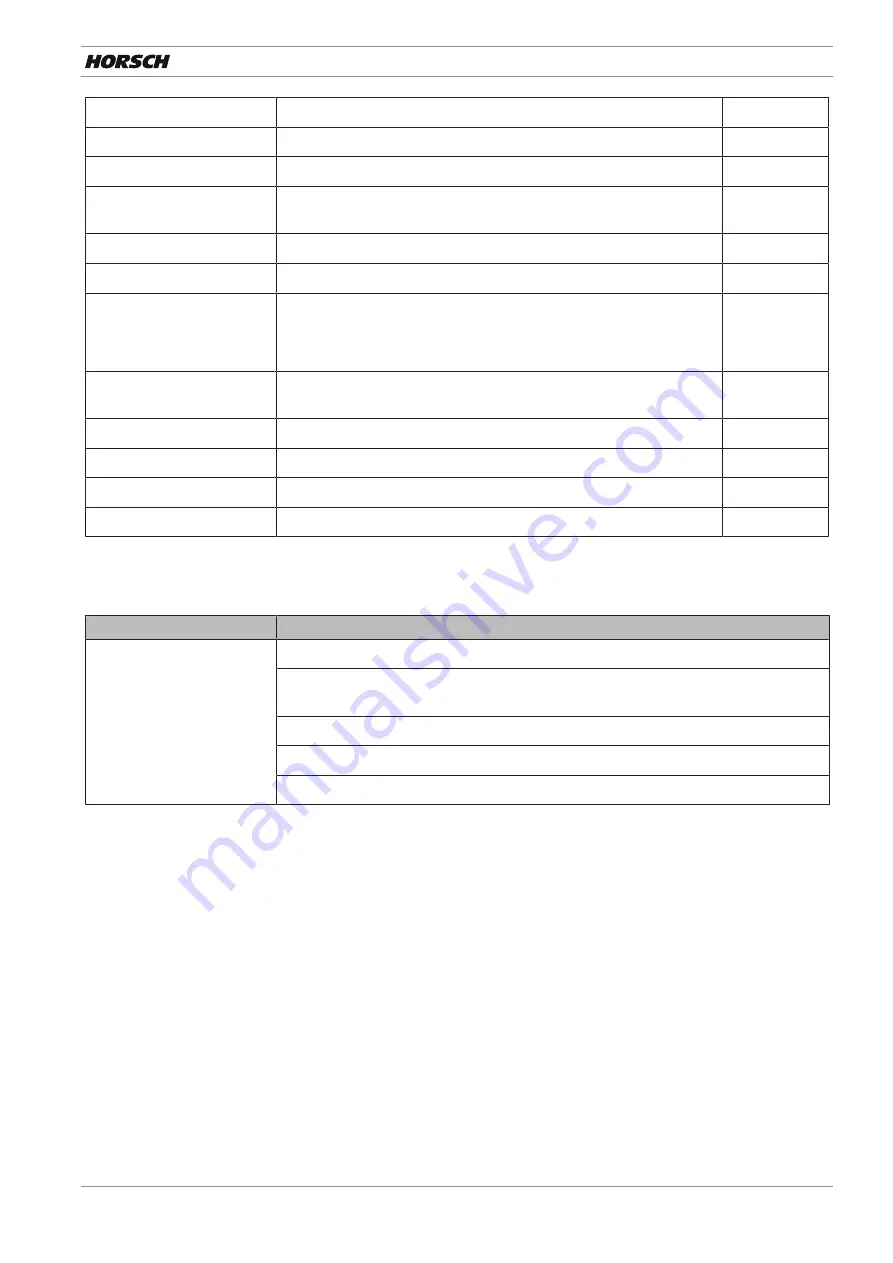
Electrics
Electric lines
Check for damage
40 h
Hydraulics
Hydraulic system and com-
ponents
Check all hydraulic components and hoses for function, leak tight-
ness, fastening and chafing.
40 h
Wheels
All wheels
Check for damages (cracks, etc.) and wear and replace if necessary.
daily
All wheels
Retighten all wheel nuts.
M18 x 1.5 – 300 Nm [221 ft.lb]
M22 x 1.5 – 510 Nm [376 ft.lb]
50 h
Bearings of carrying axle
journals
Check clearance and adjust if necessary (workshop work)
120 h /
6 months
Support wheels 23x10.50-12 Check air pressure and adjust if necessary: 3.0 bar [44 psi]
daily
Safety installations
Lighting and warning boards Check condition and function
daily
Warning and safety stickers
Check that they are in place and legible
40 h
8.1.4 At the end of the season
Maintenance location
Work instructions
Complete machine
Perform care and cleaning work; do not spray plastic parts with oil or similar.
Spray the piston rods of the hydraulic cylinder with a suitable corrosion protection
agent.
Check all screw and plug-and-socket-connections for firm seating (see torque table)
Check frame and connecting pieces for condition and tight fit.
Check electrical lines for damage and replace, if necessary.
Summary of Contents for Finer SL
Page 2: ......
Page 24: ...4 Technical data 24 60056796 002 07 2021 en Finer 6 SL 2520 2700 5960 6310 3060 3260 4590...
Page 55: ...60056796 002 07 2021 en 55 Notes...
Page 56: ...56 60056796 002 07 2021 en...
Page 57: ......


