background image

Chapter 5  mV Measurement 

62

HORIBA

Chapter 5  mV Measurement

This section describes the procedures to set the conditions of mV measurement.

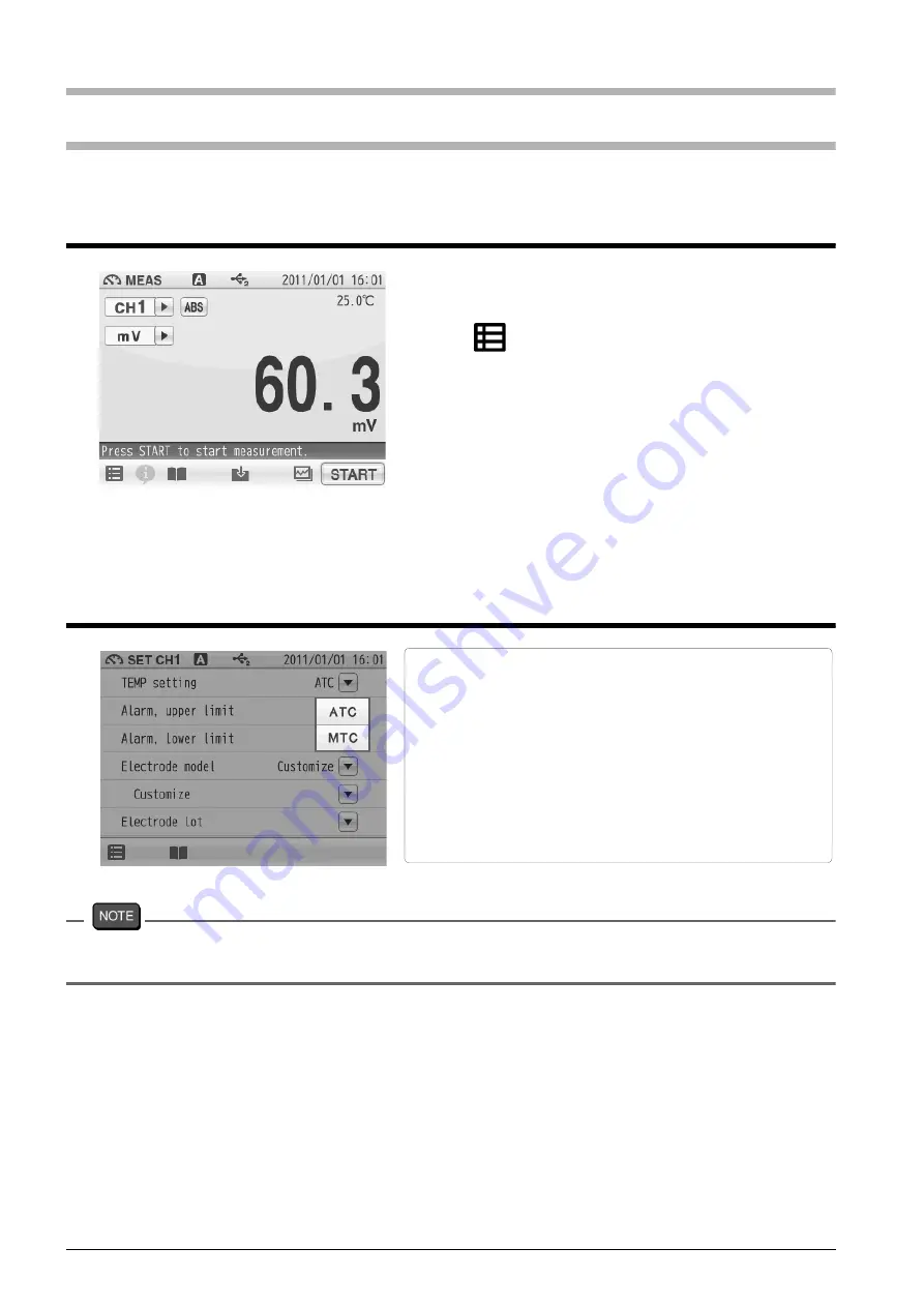
5.1 mV Measurement Setting

5.2 Temperature Setting

If the temperature terminals of the instruction and electrode are not connected, 
temperature setting is performed in MTC even when ATC is set.

1.

Tap the channel setting and the measurement 
item in the MEAS screen to set "CH1" and "mV".

2.

Tap 

 and tap "CH1 MEAS SET".

3.

mV measurement setting items are displayed.
When setting item increased, you will see the 
remaining items by dragging.

4.

Select items and set the conditions.

The setting procedures for each item are 
explained below.

There are two types of temperature setting for mV 
measurement; Automatic Temperature setting 
(ATC) and Manual Temperature setting (MTC).
In ATC, the instrument detects the solution 
temperature with the connected temperature 
sensor, and displays it on the screen. 
In MTC, measure the solution temperature and 
enter the value in advance. The instrument 
displays the entered temperature.

Summary of Contents for F-70 Series

Page 1: ...Instruction Manual pH ION METER F 73 表紙は別途デザインの表紙とする ...

Page 2: ...n attributable to repair or modification by any person not authorized by HORIBA Ltd Any malfunction or damage attributable to the use in an environment not specified in this manual Any malfunction or damage attributable to violation of the instructions in this manual or operations in the manner not specified in this manual Any malfunction or damage attributable to any cause or causes beyond the re...

Page 3: ...symbol with underbar shown on the product or accompanying documents indicates the product requires appropriate treatment collection and recycle for waste electrical and electronic equipment WEEE under the Directive 2002 96 EC and or waste batteries and accumulators under the Directive 2006 66 EC in the European Union The symbol might be put with one of the chemical symbols below In this case it sa...

Page 4: ...hese limits are designed to provide reasonable protection against harmful interference when the equipment is operated in a commercial environment This equipment generates uses and can radiate radio frequency energy and if not installed and used in accordance with the instruction manual may cause harmful interference to radio communications Operation of this equipment in a residential area is likel...

Page 5: ...d is to be limited to the most extreme situations This indicates a potentially hazardous situation which if not avoided could result in death or serious injury This indicates a potentially hazardous situation which if not avoided may result in minor or moderate injury It may also be used to alert against unsafe practices Without safety alert indication of hazardous situation which if not avoided c...

Page 6: ...cals Some ion electrodes are used with hazardous standard solutions Handle them with care If the internal solution comes in contact with the skin wash it off immediately If it gets into eyes flush with plenty of water and then consult a doctor Harmful chemicals The internal solution of an electrodes is highly concentrated potassium chloride 3 33 mol L KCl If the internal solution comes in contact ...

Page 7: ...t the cable it may cause a breakage The touch panel is capacitance type Make sure to turn OFF the power before cleaning the panel If you wipe it with the power ON it may cause instrument malfunction RS 232C or USB communication between the instrument and a per sonal computer may fail because of environmental conditions such as radio electromagnetic noise Environmental conditions for use and storag...

Page 8: ...anual This interprets the necessary points for correct operation and notifies the important points for handling the instrument This indicates the part of where to refer the information This indicates reference information MANUAL INFORMATION HINT ...

Page 9: ...onnecting the Power Source 13 1 8 Connecting the Printer 13 1 9 Connecting the Personal Computer 14 1 10 Turn on the Power 15 Chapter 2 Before Measurement Meter SET 16 2 1 Meter SET Screen 16 2 2 Auto Hold Setting 16 2 3 Custom Setting 17 2 4 Sample Name Setting 18 2 5 Interval Memory Setting 19 2 6 USB Memory Setting 20 2 7 Printer Setting 22 2 8 Screen Settings 24 2 9 Sound Setting 26 2 10 Langu...

Page 10: ... 3 10 1 Electrode Model Selection 47 3 10 2 Electrode Model Entry 47 3 11 Electrode Lot No Setting 48 3 12 pH Measurement 49 Chapter 4 ION Measurement 50 4 1 ION Calibration Setting 50 4 1 1 Calibration Points Setting 50 4 1 2 Checking Before Use 51 4 2 ION Calibration 52 4 2 1 Calibration Preparation 52 4 3 Checking Before Use 54 4 4 ION Measurement Setting 55 4 5 ION Measurement Unit Setting 55 ...

Page 11: ...1 Electrode Model Selection 71 6 5 2 Electrode Model Entry 71 6 6 Electrode Lot No Setting 72 6 7 ORP Measurement 73 Chapter 7 Application Mode 74 7 1 Standard Addition Method Mode 74 7 1 1 Measurement Using Standard Addition Method 74 7 1 2 Known Addition Method and Sample Addition Method 74 7 1 3 General Cautions for Standard Addition Method 75 7 1 4 Standard Addition Method MEAS screen 75 7 1 5...

Page 12: ...asured data_Search 91 9 5 Cal results_All 92 9 6 Copy all Meas Data 92 9 7 Delete all meas Data 93 9 8 Delete all cal data 93 Chapter 10 Specifications 94 10 1 Specifications 94 10 2 Default Settings 95 10 2 1 Meter Default Settings 95 10 2 2 Measurement Condition Default Settings Can be set per operator 96 10 3 Options 100 ...

Page 13: ... of the instrument 1 1 Description of Each Part 1 1 1 Rear 1 1 2 Display CH2 reference electrode CH2 measurement electrode CH2 for temperature electrode CH1 reference electrode CH1 measurement electrode CH1 for temperature electrode CAL key POWER key MEAS key DATA key Icon bar Status bar Touch panel ...

Page 14: ...er Protects the instrument side surfaces Instruction manual Instructs the usage of the instrument Quick manual Instructs the operations of calibration and measurement Ferrite core Attach this device to the AC adapter cable to reduce interference AC adapter connector Serial communication connector RS 232C Analog output connector 1 CH1 data Analog output connector 2 CH2 data Analog output connector ...

Page 15: ...e AC adapter is connected Wait for a while after connecting AC adapter Operation key Function POWER Turns ON or OFF the power Press and hold for 2 seconds or more CAL Displays the calibration screen CAL screen MEAS Displays the measurement screen MEAS screen DATA Displays the data screen DATA screen ...

Page 16: ...k operation instructions and information about measurement and maintenance Printer Used to print out measurement or calibration values or saved data when a printer is connected Save in USB Used to save measured data into a USB memory Save data Used to save measurement values displayed on the screen into the instrument 2CH simultaneous graph Used to check both the measurement values of CH1 and CH2 ...

Page 17: ...d automatically according to input signals from the electrode based on the pre selected stability criterion of measurement values Refer to 2 2 Auto Hold Setting P 16 Manual hold Shows that the manual hold function is ON and that the end point is determined manually Refer to 2 2 Auto Hold Setting P 16 USB1 1 Shows that the instrument is connected with a personal computer via a USB cable USB2 1 Show...

Page 18: ...is the electrode temperature ATC Not displayed The displayed temperature is preset value MTC HOLD indicator Not displayed An instantaneous value is displayed Blinking In process for HOLD Lighting up HOLD completed Temperature HOLD indicator Channel Icon Measurement mode Status Date and time Measurement item Temperature compensation electrode connection indicator Measurement values Measurement oper...

Page 19: ...ons Operation Description Tap Tap on the screen lightly once with a finger Tap a menu item or icon to select it or change settings Flick Touch and flick on the screen with a finger Used to switch to the digital or graph display on the MEAS or CAL screen Drag Keep a finger in contact with the screen and drag it on the screen Used to search a setting item or measurement data on the DATA screen When ...

Page 20: ...splay methods to check variation and tendency of measurement values You can shift the screen to the digital graph or analog screen by flicking it Digital display If arrows like and appear when you touch the screen you can flick in the directions to switch the screen display Graph display Analog display ...

Page 21: ...you to check a small change in measurement values Tap on the screen after the above operations and the latest data will be displayed in optimized range The vertical axis is zoomed in The displayed range narrows The vertical axis is zoomed in The displayed range narrows Displays the next or the latest data Displays the previous data The displayed range narrows It allows you to check the detailed va...

Page 22: ... a deviation between the maximum and minimum values in the last 10 seconds For example you will make a good pH calibration during the stability value is 0 002 or less though it depends on measurement environment Graph display Flick the screen during calibration to shift to the graph display Digital display Graph display If arrows like and appear when you touch the screen you can flick in the direc...

Page 23: ...nd 1 Attach the stand shaft to the stand base 2 Attach the stopper and the stand arm to the stand shaft The width of measurement range becomes narrower to enlarge the display of measurement values The width of measurement range becomes wider to reduce the display of measurement values Displays the next or the latest data Displays the previous data Stand base Stand shaft Stand arm Stopper ...

Page 24: ...tor socket pin of the instrument Do not insert it with force when the pin and groove are misaligned 2 Turn the electrode connector to the right along the groove to plug the connector 3 Put the connector cover on the connector Just push the cover on the instrument Do not screw in it 1 Insert the temperature connector into the jack socket on the instrument CH2 reference electrode CH2 measurement ele...

Page 25: ...onnector socket on the instrument Setting the Printer Refer to the instruction manual of the printer for settings and operations of the printer 1 Set the DIP switch No 6 to ON and No 7 to OFF and then set printer paper and ink ribbon Keep the LF key held down 2 Keep the SEL key held down The printer prints output when the SEL key is being pressed 1 Insert the AC adapter cable by fitting with the c...

Page 26: ...easuring instrument and personal computer are same Otherwise communication may fail due to a communication error or the online mode start failure If you change the transfer formats power OFF both of the instrument and the personal computer once and then turn ON them again For the details of communication commands register with our website and see the free download page of manuals USB connector for...

Page 27: ...layed The POWER key does not work for 10 seconds after the AC adapter is connected Wait for a while after connecting AC adapter If the following message appears on the screen during operation disconnect the AC adapter and then connect it again and power ON the instrument F 7X series memory manager Exception failure occurred Please detach AC adapter and restart ...

Page 28: ...the conditions The setting procedures for each item are explained below 1 Change the auto hold settings tap on the right of the AUTO HOLD item 2 Tap on the right of the HOLD TYPE item 3 Select the measurement stability condition of the 6 types EXACT NORMAL BRIEF TIME CUSTOMIZE Manual in the AUTO HOLD selection screen To cancel the operation tap to return to the previous screen In the AUTO HOLD mod...

Page 29: ...ment item Tap to return to the previous screen Mode Measuring target Content Time s Temperature C Criteria Default EXACT pH 10 2 0 0 005 pH Equivalent to 0 3 mV ION mV ORP 0 3 mV NORMAL pH 10 2 0 0 015 pH Equivalent to 1 0 mV Default setting of auto hold ION mV ORP 1 0 mV BRIEF pH 10 2 0 0 050 pH Equivalent to 3 0 mV ION mV ORP 3 0 mV TIME Common Arbitrarily set at 2 s to 999 s 10 s CUSTOMI ZE pH ...

Page 30: ...the right of the Sample name item 2 Tap on the right of the item in the CH1 or the CH2 to enter the sample name 3 Tap to switch the keyboard entry screen of Alphabet Numerical Symbol Tap to input in lower case alphabets Up to 10 characters can be input 4 Tap The setting applies To cancel the settings tap Tap to return to the previous screen You can set sample names for CH1 and CH2 ...

Page 31: ... right of the Interval memory item and select ON 1 Display the Time item when select ON Tap on the right of the Time item 2 Enter the interval time in the numerical key screen Setting range 1 to 999 sec 3 Tap The setting applies To cancel the settings tap The measured data can be stored at set time intervals ...

Page 32: ...ayed Tap to return to the previous screen 1 Tap on the right of the Simultaneously memory item and select ON 1 Tap on the right of the Eject item and tap in the execution confirmation screen To cancel the operation tap 2 When the ejection is completed a notice message will appears Tap Memory data can be written into a USB memory When a USB memory is inserted into the instrument the data can be wri...

Page 33: ...message that formatting is in progress appears during formatting Do not remove the USB memory and do not disconnect the instrument power while this message appears The instrument and USB memory are being accessed 2 When the format is completed a notice message will appears Tap Use this item to format a USB memory in FAT16 Note that formatting deletes all stored data ...

Page 34: ...ut item and select ON 1 Tap on the right of the Printout Layout item The printing format screen is displayed Tap to return to the previous screen The Printer item allows you to set printing contents etc effective only when a printer is connected with the instrument When a printer is connected with the instrument this item allows you to perform a printer test When a printer is connected with the in...

Page 35: ... you want to print out among the GLP printing contents But measurement values are always printed 1 Select CUSTOMIZE from Printout Layout and tap on the right of the each printing item is ON The item is selected is OFF The item is not selected CUSTOMIZE allows you to select items you want to print out among Measurement date time User name Settings Sensor info Cal User BRIEF pH measurement NORMAL pH...

Page 36: ...Screen theme item 2 Select screen theme To cancel the operation tap to return to the previous screen 1 Tap on the right of the Display brightness item 2 When the screen becomes the desired brightness tap To cancel the operation tap to return to the previous screen You can change screen settings You can select one among 4 type screen thems STANDARD COOL MONOTONE and KYOTO You can adjust the display...

Page 37: ... power saving mode 1 Tap on the right of the Power saving mode item and select ON When selecting ON for Power saving mode the Back light off time item is displayed 1 Tap on the right of the Back light off time item 2 Enter the desired time on the numerical key screen Setting range 1 to 999 minutes 3 Tap The set time applies To cancel the settings tap You can set the time for power saving mode ...

Page 38: ...eme To cancel the operation tap to return to the previous screen 1 Tap on the right of the Sound volume set tings item 2 When the screen becomes the desired volume tap To cancel the operation tap to return to the previous screen You can change sound settings You can select one among 4 type sound thems STANDARD COOL MONOTONE and KYOTO You can adjust the sound volume by tapping or or by dragging on ...

Page 39: ...t ON You can change language settings Security setting allows you to set a password for an administrator of the instrument After the setting is ON the instrument requires you to select an operator name at the startup Security setting Date Time setting Analog output adj Temp calibration and Meter initialization are restricted to the administrator To change the administrator or operator when the Sec...

Page 40: ...strator s names are marked with a star on the user selection screen 1 Tap the blank area at the right of User name to display the letter entry screen 2 Enter the operator name and tap Tap the to switch the keyboard entry screen of Alphabet and Numerical Symbol Tap the to input in lower case alphabets Up to 12 characters can be input 3 Tap the blank area at the right of Password to display the nume...

Page 41: ...en ia dis played To cancel the operation tap to return to the previous screen 1 Tap on the right of the User entry item 2 Tap the blank area at the right of User name to display the letter entry screen 3 Enter the operator name and tap Tap the to switch the keyboard entry screen of Alphabet and Numerical Symbol Tap the to input in lower case alphabets Up to 12 characters can be input 4 Tap the bla...

Page 42: ...word to display the numerical key screen 4 Enter the password and tap The password can be set between 2 and 10 characters 1 Tap on the right of the User delete item 2 Tap on the right of the operator item 3 Tap Tap when do not deleting 1 Tap on the right of the Administrator entry item 2 Tap to add a new administrator at the Administrator entry screen Then the lights up to show it is in the state ...

Page 43: ...o return to the previous screen 1 Tap on the right of the Year month day item 2 Tap or to set the date 3 Tap To cancel the operation tap to return to the previous screen 1 Tap on the right of the hour min item 2 Tap or to set the time 3 Tap To cancel the operation tap to return to the previous screen You can set the date and time You can set the date You can set the time ...

Page 44: ... The Output value adjustment screen is dis played 2 Tap or to adjust the analog output volt age 3 Tap To cancel the operation tap to return to the previous screen Voltage output can be acquired from the analog output connector located at the instrument side Connect the instrument with a digital multimeter digital recorder pen recorder or the like using an designated cable analog output cable Parts...

Page 45: ... operation tap to return to the previous screen 2 Display the measured temperature by the temperature sensor connected to the instrument Display when not connecting the temper ature sensor 3 Tap on the right of the temperature sensor s channel item 4 Enter the temperature with the numerical screen and tap Tap when do not reflect the setting You can perform calibration of the temperature sensor ...

Page 46: ...e after reconnecting AC adapter 1 Tap on the right of the Meter initialization item 2 Tap in the execution confirmation screen Tap when do not resetting 3 Display the confirmation screen again and tap Tap when do not resetting 4 Restart after the Meter initialization was finished Press the POWER key to turn OFF 5 Press and hold the POWER key for 2 seconds to turn ON You can reset the instrument to...

Page 47: ...et the conditions The setting procedures for each item are explained below 1 Tap on the right of the Standard Solution item and tap the standard solution in the selec tion screen The setting applies The check mark on the cur rent setting item is displayed To cancel the settings tap 1 Tap on the right of the Calibration Points item 2 Tap or in the Calibration points setting screen to set the calibr...

Page 48: ...ight of the Calibration Interval item to set the calibration interval 2 Tap 1 Display the Cal Interval item when select ON at the calibration interval Tap on the right of the Cal Interval item 2 Enter the interval day in the numerical key screen 3 Tap The setting applies To cancel the settings tap You can set the number of days between calibrations to the initiate an alert ...

Page 49: ... the Checking Before Use setting to ON it allows you to check repeatability after calibration by comparing the measured value of pH7 standard solution with the calibration result After the set point calibrations are completed repeatability is automatically checked using the deviation between the calibrated and measured values at pH7 For example the sequence for the 2 points cali bration by pH7 and...

Page 50: ...ing pH4 pH7 and pH9 when the sample is unknown For calibration other than that by 2 points change the calibration point setting Tapping on the pH CAL screen allows you to check the current calibration data To clear the calibration data tap As an example the procedures of 2 points calibration using pH4 and pH7 standard solutions are as follows 3 2 1 Calibration Preparation 1 Tap the channel setting...

Page 51: ... while the HOLD indicator blinks The brinking interval of the HOLD indicator may not be constant depending on the reading stability level When the reading stabilizes the value is held and the progress bar shows that the pH7 cali braion is completed 2 After the 1st point calibration is completed tap to proceed to the 2nd point calibration 1 Wash the pH electrode with pure water ion exchange water a...

Page 52: ...reen Display Sensitivity Description Good 90 to 105 You can use it without any problem Electrode check 85 to 90 Wash the electrode If the sensitivity does not improve after recalibration replace the electrode Electrode NG 85 or less than This appears only for calibration data on the DATA screen Calibration with 85 or less sensitivity does not apply to measurement but is recorded on the DATA screen...

Page 53: ...olution is set to NIST USA or China When the standard solution is set to CUSTOM this function can not performed 1 When calibration for all of the points is completed the repeatability is automatically checked 2 This repeatability check confirms the deviation from the calibrated value by the standard solution of pH7 For example the sequence for the 2nd point cal ibration by pH7 and pH4 is as follow...

Page 54: ...Open the internal solution filler port of the pH electrode 4 Immerse the pH electrode into a beaker of pH7 standard solution 1 Tap the pH value at the right of Set to display the numerical key screen 2 Enter the pH value of the standard solution to be used for calibration and tap The entered pH value applies as the standard solution 3 Tap to start the calibration of the 1st point When the 1st poin...

Page 55: ...creen to set CH1 and pH 2 Tap and tap CH1 MEAS SET 3 pH measurement setting items are displayed You will see the remaining items by dragging 4 Select items and set the conditions You can switch the resolution for pH measurement values to 0 01 pH 0 001 pH or Auto If Auto is set the resolution is switched automatically to 0 001 pH when the variation of pH measurement value is 0 01 pH or less in the ...

Page 56: ...item 2 Enter the sample temperature on the numerical key screen 3 Tap The setting applies To cancel the settings tap There are two types of temperature compensation for pH measurement Automatic Temperature Compensation ATC and Manual Temperature Compensation MTC In ATC the instrument detects the solution temperature with the connected temperature sensor and performs temperature compensation for th...

Page 57: ...ersion item the Std Temp item is displayed Tap on the right of the Std Temp item 2 Enter a temperature as the standard temperature for conversion on the numerical key screen 3 Tap The setting applies To cancel the settings tap To use the temperature conversion function set TEMP conversion to ON The measured pH value of a sample varies with the temperature In addition the change degree with tempera...

Page 58: ...er limit alarm to ON for the lower limit control of measurement value 3 9 1 Input Alarm Upper Limit or Lower Limit Upper limit value entry Lower Limit value entry Upper limit value Lower limit value 1 When selecting ON the Alarm upper limit item the Upper limit value tap on the right of the Upper limit value item 2 Enter an upper limit value on the numerical key screen 3 Tap The setting applies To...

Page 59: ...right of the Electrode model item The electrode model selection screen appears Tap when do not reflect the setting 2 Select the electrode model to be used Tap an electrode model name and the selected model applies 1 Tap Customize in the electrode model selection screen 2 When selecting Customize for the Electrode model item the Customize item is displayed Tap on the right of the Customize item 3 E...

Page 60: ...the right of the electrode lot No enter nothing and tap 1 Tap on the right of the Electrode lot item 2 Enter the electrode lot No in the numerical screen Up to 8 digits can be entered To cancel the settings tap When an electrode lot No is entered the lot No can be displayed on data printouts or recorded in saved data ...

Page 61: ...han 3 cm from the tip Immerse the electrode tip at least 3 cm into the sample solution for an accurate measurement Refer to the instruction manual of the electrode for more details 4 Press the MEAS key and tap the channel setting and the measurement item in the MEAS screen to set CH1 and pH 5 Tap to start measurement The measurement value is displayed and the HOLD indicator blinks until the readin...

Page 62: ...and ION 2 Press the CAL key to display the ION CAL screen 3 Tap and tap CH1 CAL SET Ion calibration setting items are displayed 4 Select items and set the CONDITIONS The setting procedures for each item are explained below 1 Tap on the right of the Calibration Points item 2 Tap or in the Calibration points setting screen to set the calibration points 3 Tap The setting applies To cancel the setting...

Page 63: ...ion by comparing the measured value of pH7 standard solution with the calibration result After the set point calibrations are completed repeatability is automatically checked using the deviation between the calibrated and measured values at pH7 For example the sequence for the 2 points cali bration by pH7 and pH4 is as follows pH7 Calibration of 1st point pH4 Calibra tion of 2nd point pH7 Repeatab...

Page 64: ...the paragraph of 4 4 ION Measurement Setting P 55 The calibration calculation of an ION electrode depends on the unit and ion to be measured Perform ION measurement setting before starting calibration Tapping on the ION CAL screen allows you to check the current calibration data To clear the calibration data tap As an example the procedures of 2 points calibration using standard solutions are as f...

Page 65: ...d 5 Tap to start the calibration of the 1st point When the 1st point calibration is completed the HOLD indicator is lit up and the progress bar shows that the 1st point calibraion is completed 1 Wash the ION electrode with pure water ion exchange water and wipe it off by filter paper or tissue paper 2 Immerse the ION electrode into a beaker of the standard solution used for the 2nd point calibrati...

Page 66: ...the beginning 4 3 Checking Before Use When the preliminary check function is ON you can check repeatability with the standard solution of the 1st point calibration Use this function to check measurement accuracy by checking repeatability An operation guide is displayed after the 2nd point calibration is completed Check the repeatability according to the operation guide After the set point calibrat...

Page 67: ... measurement item in the MEAS screen to set CH1 and ION 2 Tap and tap CH1 MEAS SET 3 ION measurement setting items are displayed You will see the remaining items by dragging 4 Select items and set the CONDITIONS The setting procedures for each item are explained below 1 Tap on the right of the Unit item 2 Select g L or mol L The selected unit applies You can select g L or mol L as the ION measurem...

Page 68: ...m 2 Enter the sample temperature on the numerical key screen 3 Tap The setting applies To cancel the settings tap There are two types of temperature compensation for ION measurement Automatic Temperature Compensation ATC and Manual Temperature Compensation MTC In ATC the instrument detects the solution temperature with the connected temperature sensor and performs temperature compensation for the ...

Page 69: ...mit alarm to ON for the upper limit control of measurement value Set the lower limit alarm to ON for the lower limit control of measurement value 4 7 1 Input Upper or Lower Limit Values Upper limit value entry Upper limit value Lower limit value 1 When selecting ON the Alarm upper limit item the Upper limit value tap on the right of the Upper limit value item 2 Enter an upper limit value on the nu...

Page 70: ...ange 1 When selecting ON the Alarm lower limit item the Lower limit value tap on the right of the Lower limit value item 2 Enter an upper limit value on the numerical key screen To change the unit mg L µg L etc tap on the unit change key on the right of the numerical key screen 3 Tap The setting applies To cancel the settings tap ...

Page 71: ...ght of the Electrode model item The electrode model selection screen appears Tap when do not reflect the setting 2 Select the electrode model to be use Tap an electrode model name and the selected model applies 1 Tap Customize in the electrode model selection screen 2 When selecting Customize for the Electrode model item the Customize item is displayed Tap on the right of the Customize item 3 Ente...

Page 72: ... the left of the selected item 2 Tap or in the ionic valence setting screen to set the ION valency 3 Tap The setting applies To cancel the settings tap 1 Tap on the right of the Electrode lot item 2 Enter the electrode lot No in the numerical key screen Up to 8 digits can be entered To cancel the settings tap When the Electrode model item is set to Customize enter the valency of the ion to be meas...

Page 73: ...into the sample solution for an accurate measurement Refer to the instruction manual of the electrode for more details 4 Press the MEAS key and tap the channel setting and the measurement item in the MEAS screen to set CH1 and ION 5 Tap to start 1st point measurement The measurement value is displayed and the HOLD indicator blinks until the reading stabilizes To stop calibration tap while the HOLD...

Page 74: ... mV 2 Tap and tap CH1 MEAS SET 3 mV measurement setting items are displayed When setting item increased you will see the remaining items by dragging 4 Select items and set the conditions The setting procedures for each item are explained below There are two types of temperature setting for mV measurement Automatic Temperature setting ATC and Manual Temperature setting MTC In ATC the instrument det...

Page 75: ...measurement values exceeds the alarm range the color of the pertinent channel CH is changes on the MEAS screen Set the upper limit alarm to ON for the upper limit control of measurement value Set the lower limit alarm to ON for the lower limit control of measurement value 1 Display the Temperature item when select MTC Tap on the right of the Temperature item 2 Enter the solution temperature on the...

Page 76: ...value tap on the right of the Upper limit value item 2 Enter an upper limit value on the numerical key screen 3 Tap The setting applies To cancel the settings tap 1 When selecting ON the Alarm lower limit item the Lower limit value tap on the right of the Lower limit value item 2 Enter an upper limit value on the numerical key screen 3 Tap The setting applies To cancel the settings tap ...

Page 77: ...ht of the Electrode model item The electrode model selection screen appears Tap when do not reflect the setting 2 Select the electrode model to be use Tap an electrode model name and the selected model applies 1 Tap Customize in the electrode model selection screen 2 When selecting Customize for the Electrode model item the Customize item is displayed Tap on the right of the Customize item 3 Enter...

Page 78: ...e right of the electrode lot No enter nothing and tap 1 Tap on the right of the Electrode lot item 2 Enter the electrode lot No in the numerical key screen Up to 8 digits can be entered To cancel the settings tap When an electrode lot No is entered the lot No can be displayed on data printouts or recorded in saved data ...

Page 79: ...ess the MEAS key and tap the channel setting and the measurement item in the MEAS screen to set CH1 and mV Tap to convert the potential display between ABS absolute potential and REL relative potential Tapping shifts the measured potential to zero and displays the difference in relative potential The potential without correction is called absolute potential 5 Tap to start measurement The measureme...

Page 80: ...ment item in the MEAS screen to set CH1 and ORP 2 Press the CAL key to display the ORP CAL screen 3 Wash the ORP electrode with pure water ion exchange water and wipe it off by filter paper or tissue paper 4 Open the internal solution filler port of the ORP electrode 5 Immerse the ORP electrode into a beaker of the standard solution 6 Tap the mV value at the right of Set to display the numerical k...

Page 81: ...EAS SET 3 ORP measurement setting items are displayed When setting item increased you will see the remaining items by dragging 4 Select items and set the conditions 1 Display the Temperature item when select MTC Tap on the right of the Temperature item 2 Enter the solution temperature on the numerical key screen 3 Tap The setting applies To cancel the settings tap There are two types of temperatur...

Page 82: ...ower limit alarm to ON for the lower limit control of measurement value 6 4 1 Input Upper or Lower Limit Values Upper limit value entry Lower limit value entry Upper limit value Lower limit value 1 When selecting ON the Alarm upper limit item the Upper limit value tap on the right of the Upper limit value item 2 Enter an upper limit value on the numerical key screen 3 Tap The setting applies To ca...

Page 83: ...ght of the Electrode model item The electrode model selection screen appears Tap when do not reflect the setting 2 Select the electrode model to be use Tap an electrode model name and the selected model applies 1 Tap Customize in the electrode model selection screen 2 When selecting Customize for the Electrode model item the Customize item is displayed Tap on the right of the Customize item 3 Ente...

Page 84: ...e right of the electrode model name enter nothing and tap 1 Tap on the right of the Electrode lot item 2 Enter the electrode lot No on the numerical key screen Up to 8 digits can be entered To cancel the settings tap When an electrode lot No is entered the lot No can be displayed on data printouts or recorded in saved data ...

Page 85: ... cm into the sample solution for an accurate measurement Refer to the instruction manual of the electrode for more details 4 Press the MEAS key and tap the channel setting and the measurement item in the MEAS screen to set CH1 and ORP 5 Tap to start measurement The measurement value is displayed and the HOLD indicator blinks until the reading stabilizes To stop calibration tap while the HOLD indic...

Page 86: ... method mode you can save the measurement results only to a USB memory They can also be printed out If you need to save or print out the data Simultaneously Memory of 2 6 USB Memory Setting P 20 or Auto Printout of 2 7 Printer Setting P 22 to ON in advance Refer to JIS K0122 for standard addition method 7 1 2 Known Addition Method and Sample Addition Method Known addition method For the known addi...

Page 87: ... standard solution is added Therefore it is not necessary to perform calibration or check the electric potential slope before the measurement However the following condition may affect the measurement results If the linearity of the electrode used is poor If the electric potential slope is greatly different from the theoretical values Nernst coefficient If the sample temperature shifted significan...

Page 88: ... item and range Concentration of the additive standard solution 0 1 mg L to 19000 0 mg L Volume of the additive standard solution 0 01 mL to 1000 00 mL Electrode slope 99 99 mV dec to 99 99 mV dec Sample volume 1 0 mL to 19999 9 mL HINT For more accurate measurement Normally the amount of the standard solution to be added should be from 0 1 to 10 of the sample solution It is desirable that when th...

Page 89: ...ge in electric potential at that time Measurement condition setting 1 Tap on the right of the Known addition method item in the ION standard addition mode screen 2 Tap on the right of the Known add method Double item 3 Set the measurement condition in the Known add method Double screen Enter sample volume concentration of the additive standard solution volume of the 1st and 2nd standard solution a...

Page 90: ... next measurement 7 Immerse the ion electrode in the 1 standard solution and tap The measurement starts 8 Tap to proceed to the next measurement 9 Immerse the ion electrode in the 2 standard solution and tap The measurement starts When the measurement is completed concentration of the sample and the measuring condition are displayed as measurement results Tap to return to the ION standard addition...

Page 91: ...to 10 of the sample solution It is desirable that when the standard solution is added to the sample solution the concentration of the ion species under measurement increase by 1 to 10 times in the sample solution If the concentration of the added standard solution is too low or if the volume of the added standard volume is larger than that of the sample a large error may occur in the measurement r...

Page 92: ... the set value to default tap the Setting item and range Volume of the additive sample 1 2 0 01 mL to 1000 00 mL Ion valency 2 1 1 2 Concentration of the standard solution 0 1 mg L to 19000 0 mg L Standard solution volume 1 0 mL to 19999 9 mL HINT For more accurate measurement Normally the amount of the standard solution to be added should be from 0 1 to 10 of the sample solution It is desirable t...

Page 93: ...ement 9 Immerse the ion electrode in the 2 sample solution and tap The measurement starts When the measurement is completed concentration of the sample and the measuring condition are displayed as measurement results Tap to return to the ION standard addition mode screen ...

Page 94: ...d solutions of pH7 and pH4 the measurement of the solution of pH7 is given five times and the repeatability is confirmed Simulator X 51 mode Optional pH simulator X 51 checks the meter only electrode check is not included The JIS and Pharmacopoeia modes are based on the corresponding regulations but not fully compliant with the regulations Note that the modes may not follow the regulations if the ...

Page 95: ...played according to those when the calibration is cleared When the measurement and check is completed the result data is displayed Result data output 1 Judgment OK The result data satisfies the regulation CHECK The result data does not satisfy the regulation TEMP The temperature gap is over 0 2 C 2 Calibrated value Calibrated value for each standard solution of pH7 4 and 9 potential and tempera tu...

Page 96: ...ype 1 for the pH standard solution Keep the temperature within 0 2 C by a temperature controlled bath Set the temperature in the temperature controlled bath to room temperature 25 C or equivalent Perform light stirring using the electrode stand and a stirrer Press HOLD after the measured values completely stabilizes HINT Typical time interval for the measurement values to become stabilized is 3 to...

Page 97: ...es are displayed according to those in the periodic inspection mode Perform measurement by the standard solutions in the following order 1 pH6 865 2 pH4 008 or pH9 180 3 pH6 865 4 pH6 865 5 pH6 865 6 pH6 865 7 pH6 865 Wash the electrode with pure water before each measurement The measured values during periodical check are based on the values when the calibration is cleared When the calibration ra...

Page 98: ... room temperature 25 C or equivalent Perform light stirring use the electrode stand and a stirrer to stir samples lightly Hold a measured value after it completely stabilizes HINT It takes 3 to 10 minutes for measurement values to stabilze since the electrode is immersed into the standard solution When an electrode is defective If the check result is wrong even in the above operations try followin...

Page 99: ...isplayed Result data output OK CHECK OK satisfies regulation requirements CHECK does not satisfy regulation requirements Calibration Asymmetric potential within regulated value 3 mV Sensitivity 99 to 101 of regulated value Linearity Indication error at each input regulated value 0 010 pH 1 digit High impedance Indication error at each input regulated value 0 030 pH 1 digit Temperature Indication e...

Page 100: ...t unit for ion to mol L before starting the check operation After the setting change the settings apply Follow the guidance to calibrate the instrument by simulated input of 0 mV and 120 mV in the order below and check the following operation Simulated calibration check 0 mV 1 00 mol L 120 mV 10 0 mmol L Simulated linearity check 240 mV 100 µmol L 120 mV 10 0 mmol L 0 mV 1 00 mol L 120 mV 100 mol ...

Page 101: ...Periodic Inspection Mode F 73 89 8 3 Comment Input A comment can be entered up to 100 characters Use this fuction to record periodical checks etc Tap to use the function To delete the content input previously tap ...

Page 102: ...checked by dragging the item in order 100 items of data can be viewed on 1 page 2 Tap to check other pages The next 100 items are displayed 3 Tap of the each data to check details of the data 4 Flick on a detailed data screen and the previous next detailed data screen is displayed 1 Tap on a detailed data screen DELETE is displayed under the ID number 2 Tap to return the Measured data_All screen d...

Page 103: ... input screen and tap 3 When you select Measured on enter the measurement date and tap on the next screen When you select Measuring mode tap on a measurement item on the next screen When you select User name enter operator name and tap on the next screen When you select Sample ID enter sample name and tap item on the next screen Search is performed and the result is displayed You can check just th...

Page 104: ...of the Cal results_All 2 Tap on the right of each measured items 3 Tap on the right of the data to be checked 4 After the check is completed tap to return the Cal Result_All screen 1 Tap on the right of the Copy all meas Data 2 Tap to execute the all measurement data copying Not to execute tap 3 Tap in the Copy all meas Data completion screen You can check the latest 20 data of pH and ION calibrat...

Page 105: ...DATA screen 1 Tap on the right of the Delete all cal data 2 Tap to delete the all calibration history data To cancel the operation tap 3 Tap on the Delete all cal data completion screen You can delete all measurement data saved in the instrument You can delete all calibration history data saved in the instrument If you want to delete the latest calibration data tap on the calibration screen of eac...

Page 106: ...0 01 0 001 pH Repeatability 0 001 pH 1 digit Temperature Measuring principle Thermistor method Display range 30 0 C to 130 0 C Measuring range 0 0 C to 100 0 C Resolution 0 1 C Repeatability 0 1 C 1 digit mV ORP Measuring range 1999 9 mV Resolution 0 1 mV Repeatability 0 1 mV 1 digit ION Measuring principle Ion electrode Measuring range 0 00 µg L to 999 g L mol L Resolution Valid numbers 3 digits ...

Page 107: ...F Manual NORMAL In selecting TIME Time setting value 2 seconds to 999 seconds 10 seconds In selecting CUSTOM Time setting value 2 seconds to 60 seconds 10 seconds pH variation width 0 001 pH to 0 100 pH 0 005 pH mV variation width 0 1 mV to 60 0 mV 0 3 mV ORP variation width 0 1 mV to 60 0 mV 0 3 mV Ion variation width 0 1 mV to 60 0 mV 0 3 mV Interval memory Interval memory function Enable Disabl...

Page 108: ...TC Automatic temperature compensation MTC Manual temperature compensation ATC Temperature input value in selecting MTC 0 0 C to 100 0 C 25 0 C Temperature conversion Temperature conversion function Enable Disable Disable Temperature conversion coefficient 0 100 pH C 0 000 pH C Standard temperature 0 0 C to 100 0 C 0 0 C Electrode data Model None lot No None pH calibration condition Standard soluti...

Page 109: ...re input value in selecting MTC 0 0 C to 100 0 C 25 0 C Electrode data Model None lot No None mV measurement condition Alarm condition Upper limit value setting Enable Disable Disable Lower limit value setting Enable Disable Disable Upper limit value 1999 9 mV 1999 9 mV Lower limit value 1999 9 mV 1999 9 mV Temperature setting Temperature setting ATC Automatic temperature compensation MTC Manual t...

Page 110: ...unit g L mol L g L Ion valency 2 1 1 2 1 Ion type 1 Na K NH4 Ag X 1 CN Cl I Br SCN F NO3 2 Cu Cd Pb Ca X2 2 S2 X2 X Temperature setting Temperature setting ATC Automatic temperature compensation MTC Manual temperature compensation ATC Temperature input value in selecting MTC 0 0 C to 100 0 C 25 0 C Electrode data Model None lot No None Ion calibration condition Calibration points 1 to 5 points 2 p...

Page 111: ...10 5 Power saving mode Enable Disable Disable Back light off time 1 to 999 minutes 60 minutes Sound setting Volume 0 to 9 5 Sound theme STANDARD1 STANDARD2 AQUA KYOTO STANDARD1 Printer setting Automatic printing Enable Disable Disable Printing format BRIEF NORMAL GLP CUSTOMIZE NORMAL USB memory Simultaneous memory Enable Disable Disable Item Selection item Setting range Default values ...

Page 112: ...able EU 230 V 3014031952 Plain paper printer Printer USA 120 V 3014030146 Printer cable sold separately Printer EU 230 V 3014030147 Printer cable 3014030148 1 5 m Roll paper 3014030149 20 rolls set Ink ribbon 3014030150 5 pcs set USB cable 3200373941 1 m Serial cable 3014030151 Analog alarm output cable 3014030152 Electrode stand Standard type 3200382557 Electrode stand Long type 3200382560 Stand ...

Page 113: ...For any question regarding this product please contact your local agency or inquire from the Customer Registration website http www horiba com register 1st edition October 2011 CODE GZ0000260895 ...

Page 114: ...表紙は別途デザインの表紙とする ...

Reviews: