background image

6 FUNCTIONALITIES

71

Changing the IP address

1.

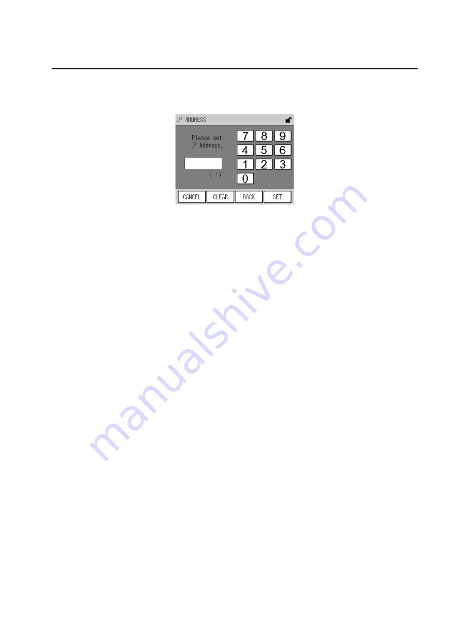
Press the IP ADDRESS button.

The IP ADDRESS screen will be displayed.

Fig. 91  IP ADDRESS screen

The currently set IP address is displayed in parentheses below the edit box.
Use the numeric keypad to enter a value in the following range:

The keys allow you to perform the following operations.

2.

Use the numeric keypad to enter a desired value.

3.

Press the [SET] key. You will return to the TCP/IP SETTING screen.

At this stage, the changed setting is not reflected. For the reflection of the setting, see " 

Reflecting the TCP/IP setting" (page 74).

[Setting range]: 0 to 255

[CANCEL]:

Returns to the TCP/IP SETTING screen without changing the setting.

[CLEAR]:

Deletes the value entered in the edit box.

[BACK]:

Deletes the previously entered value (1-digit).

[SET]:

Establishes  the  changed  value  and  then  returns  to  the  TCP/IP
SETTING screen.

Summary of Contents for APSA-370

Page 1: ...Ambient SO2 monitor APSA 370 Operation Manual CODE GZ0000051251C...

Page 2: ...of the following cases none of the warranties set forth herein shall be extended Any malfunction or damage attributable to improper operation Any malfunction attributable to repair or modification by...

Page 3: ...accumulators under the Directive 2006 66 EC in the European Union The symbol might be put with one of the chemical symbols below In this case it satisfies the requirements of the Directive 2006 66 EC...

Page 4: ...nd used in accordance with the instructions may cause harmful interference to radio communications However there is no guarantee that interference will not occur in a particular installation If this e...

Page 5: ...reme situations This indicates a potentially hazardous situation which if not avoided could result in death or serious injury This indicates a potentially hazardous situation which if not avoided may...

Page 6: ...ations of your country for disposal of the product Description in this manual Note This interprets the necessary points for correct operation and notifies the important points for handling the unit Re...

Page 7: ...screen 12 4 1 3 Screens for value setting 13 4 2 Preparation for Calibration 14 4 2 1 Entering the span gas concentration value 14 4 3 Automatic Calibration AIC 16 4 3 1 AIC setting 16 4 3 2 Precautio...

Page 8: ...Menu 55 6 5 1 Time adjustment 56 6 5 2 AIC setting 56 6 5 3 AIC sequence setting 56 6 5 4 Integration reset setting 57 6 5 5 Unit conversion factor 58 6 6 System Menu 60 6 6 1 LCD setting 60 6 6 2 To...

Page 9: ...1 2 Contact input 88 9 1 3 Contact output 89 9 1 4 Alarm output 89 9 1 5 Analog output 89 9 1 6 Power shutoff output 89 10 APPENDIX 90 10 1 Measurement Principle 90 10 2 Specification 91 10 3 Unpackin...

Page 10: ......

Page 11: ...and average optional The default setting is the combination of momentary value and rolling average Addition of an RS 232C port optional will allow you to carry out data communication 1 2 System Confi...

Page 12: ...measured values alarms etc and touch keys for operation 3 RS 232C output port Used for maintenance and adjustments 4 Sample filter A filter for the sample line Replace this filter about every 2 weeks...

Page 13: ...Sample inlet The sample gas inlet with a connector for a Teflon tube of 6 mm O D 4 mm I D Make sure that the sample gas pressure stays stable within 490 Pa In order to prevent condensation from occur...

Page 14: ...es not affect the warm up process If the ALARM key is still illuminated 3 hours later see 8 2 Alarm List page 82 to take action Since the end of warm up is not displayed it is recommended to warm up a...

Page 15: ...to disable the data logging capability before turning OFF the power so that the power is not turned OFF during access to the CF Turning OFF the power during access to the CF may damage the data in CF...

Page 16: ...3 3 Setting the AIC sequence page 22 Output setting Set the analog output range Fixed Auto or External The default setting is Auto Select a desired mode in accordance with your use 6 4 Range Menu page...

Page 17: ...se of the standard specifications the MNT Maintenance signal is outputted when the maintenance switch is ON Fig 7 Mode icon 1 Icon display area 2 Current time 3 KEY LOCK icon button 4 Range display 5...

Page 18: ...In this state pressing this button displays the KEY LOCK screen Fig 96 on page 75 allowing you to lock unlock the keys Fig 10 KEY LOCK icon button When the keys are locked you cannot operate with the...

Page 19: ...played unit is different from the factory setting the range is changed to RX X The concentration ranges are named as 1 2 3 and so forth in the ascending order AUTO Displayed when the automatic range f...

Page 20: ...for line switching is used Active measurement line The currently selected measurement line is displayed ZERO The zero gas line is now being selected SPAN The span gas line is now being selected MEAS T...

Page 21: ...e are two methods available for the manual calibration one uses the calibration gas line and the other supplies the calibration gas to the measured gas line 4 1 Calibration related Screens This sectio...

Page 22: ...4 1 3 Screens for value setting page 13 4 Span calibration coefficient The entered span calibration coefficient is displayed Press the displayed span calibration coefficient the SPAN ADJUST screen wil...

Page 23: ...arest value in the settable range MEAS To use the MEAS line select this button SPAN To use the SPAN line select this button ZERO To use the ZERO line select this button EXTERNAL To use the external co...

Page 24: ...The MODE screen will be displayed Fig 17 MODE screen 2 Select the measurement line corresponding to the line to be used for the calibration For manual calibration using the calibration gas line SPAN F...

Page 25: ...following operations 5 Enter a span gas concentration via the numeric keypad 6 Press the SET key to return to the CAL screen item Settable range Span Conc value 00001 to 99999 CANCEL Returns to the CA...

Page 26: ...ethod of AIC start Pressing the displayed AIC MODE setting will display the AIC MODE screen Fig 21 on page 17 START TIME Used to set the time for starting the next AIC sequence When the internal clock...

Page 27: ...en to return to the MENU screen AIC MODE Specify the method of starting the AIC Pressing the displayed AIC MODE setting will display the AIC MODE screen Fig 21 AIC MODE screen Press the button of the...

Page 28: ...s to be within the range Once the AIC sequence starts the START TIME setting will be changed to the expected START TIME of the next AIC the current START TIME INTERVAL If the calculated time does not...

Page 29: ...Press the value to be changed The value will be highlighted allowing you to change it Using the and buttons change the value Note When you do not use the LIMIT START END function select the default va...

Page 30: ...the value to be changed The value will be highlighted allowing you to change it Using the and buttons change the value Note INTERVAL should be set to the AIC sequence time plus 10 minutes or longer If...

Page 31: ...he END time whichever is farther from the calculated time of the closest LIMIT START END to the calculated time Fig 25 Automatic correction of START TIME based on the LIMIT START END setting An exampl...

Page 32: ...QUENCE screen will be displayed Fig 28 AIC SEQUENCE screen Item Settable range Description WAIT 0 min to 999 min Set the waiting time for stabilization after changing gas The recommended setting is 20...

Page 33: ...the SET key The setting will be changed and the AIC SEQUENCE screen will be displayed again Note Any process for which time is set to 0 min is skipped and the AIC sequence proceeds to the next step F...

Page 34: ...4 CALIBRATION 24 An example of the AIC sequence is shown in the following diagram Fig 31 An example of the AIC sequence...

Page 35: ...ES button The preset AIC sequence will start While the AIC sequence is in progress the CAL screen is displayed again and the AIC mode icon blinks Pressing the AIC key in this state displays the AIC ab...

Page 36: ...ion gas line When using the measured gas line Reference page Gas line connection check Span value setting page 14 Measurement line switching MEAS ZERO Measurement line check MEAS page 27 Zero gas intr...

Page 37: ...SET key on the CAL screen is valid only when MODE is set to MEAS or ZERO 4 Press the YES button The zero calibration will be started After the calibration is completed the zero calibration coefficien...

Page 38: ...N SET key on the CAL screen is valid only when MODE is set to MEAS or SPAN 4 Press the YES button The span calibration will be started After the calibration is completed the span calibration coefficie...

Page 39: ...tion gas line display the MODE screen and change the measurement line to MEAS When using the measured gas line supply the sample gas to the measured gas line 2 Press the CLOSE key on the CAL screen Th...

Page 40: ...screen to display the MENU DATA screen and then press the button of the data to be displayed Fig 39 MENU DATA screen The buttons allow you to perform the following operations AVERAGE 1 to AVERAGE 3 Di...

Page 41: ...n an alarm occurred the alarm icon is displayed For the details of the alarm icon see Alarm icon Checking the data alarm status page 81 If no data is recorded the following message appears Fig 41 Mess...

Page 42: ...Lock page 75 2 Display the data to be deleted on the screen for data check and press the DELETE key The message confirming data deletion will appear Fig 42 Message confirming data deletion 3 Press the...

Page 43: ...ime displayed on the AVERAGE screen is the final data acquisition time Pressing the AVERAGE 1 AVERAGE 2 or AVERAGE 3 on the MENU DATA screen displays the screen showing the latest data Fig 44 AVERAGE...

Page 44: ...ntegration or rolling average data is displayed no data will be recorded If the internal clock is put back The subsequent operation depends upon the corrected time If the corrected time is the same as...

Page 45: ...s are not displayed For the other screen functionalities see Screens for data check page 31 Integration calculation In the case of the standard specification the timing of the integration calculation...

Page 46: ...on the corrected time If the corrected time is the same as or later than the start time of the ongoing integration calculation the integration calculation will go on If the corrected time is earlier t...

Page 47: ...played on the ROLLING AVERAGE screen as time passes Fig 46 ROLLING AVERAGE screen For the screen functionalities see Screens for data check page 31 Rolling average calculation The momentary value at t...

Page 48: ...49 Displaying lamp history see page 50 Setting the analog output range see page 52 Setting the current time see page 56 Setting the AIC see page 16 Setting the AIC sequence see page 22 Selecting the i...

Page 49: ...are available DATA Fig 39 on page 30 HISTORY Fig 48 on page 40 MAINTENANCE Fig 55 on page 44 RANGE Fig 65 on page 52 SETTING Fig 70 on page 55 SYSTEM Fig 75 on page 60 COMMUNICATION Fig 85 on page 66...

Page 50: ...e following operations Operation of the HISTORY screens The common functionalities to the HISTORY screens are described below On the MENU HISTORY screen press the button for the history to be displaye...

Page 51: ...eted A message will appear confirming the data deletion Fig 50 Message confirming data deletion 2 Press the YES button The message of deleting data will be displayed and the data deletion will start A...

Page 52: ...be displayed Fig 52 CAL ADJUSTMENT HISTORY screen For the screen functionalities see Operation of the HISTORY screens page 40 6 2 2 Alarm history Press the ALARM HISTORY button on the MENU HISTORY scr...

Page 53: ...nce If an alarm occurs within the AIC sequence period the alarm record is also displayed with the history data Data time differs depending on the status of AIC sequence Refer to Table 2 Data time Tabl...

Page 54: ...the specification integration value for the standard specifica tion are displayed as buttons Note All outputs are always in the MEAS mode the current measured value is being outputted first ANALOG OUT...

Page 55: ...CLOSE key to return to the MENU MAINTENANCE screen Note Pressing the CLOSE key will put all the output back to the measured values CLOSE Returns to the MENU MAINTENANCE screen ZERO Displays the DA AD...

Page 56: ...be adjusted The selected point value will be highlighted 3 Change the point value by pressing the or button 4 To establish all the point values press the OUTPUT key 5 Press the CLOSE key to return to...

Page 57: ...cted point value will be highlighted 3 Change the point value by pressing the or button 4 To establish all the point values press the OUTPUT key 5 Press the CLOSE key to return to the ANALOG OUTPUT sc...

Page 58: ...Returns to the MENU MAINTENANCE screen Displays the previous page Displays the next page Signal name Unit Description SIGNAL mV Voltage of the measured SO2 value LAMP mV Voltage of the light intensit...

Page 59: ...perform the following operations Changing the operating hours resetting 1 Press the button of the operating hour to be changed reset The HOUR METER screen for setting will be displayed Fig 61 HOUR ME...

Page 60: ...the lamp voltage at that time are displayed under the respective control buttons The difference between the two lines is displayed at the central part Note The area below the horizontal line of the gr...

Page 61: ...data deletion will appear Fig 63 Message confirming data deletion 2 Press the YES button The message of deleting data will be displayed and the data deletion will start After the data deletion is comp...

Page 62: ...UT RANGE screen will be displayed Fig 66 ANALOG OUTPUT RANGE screen ANALOG OUTPUT1 This screen shows the current range status of each analog output signal The currently used range type is displayed on...

Page 63: ...o be changed The RANGE screen will be displayed Fig 67 RANGE screen OUTPUT 1 The range is set by choosing a button of range setting The keys allow you to perform the following operations Tip Among the...

Page 64: ...LOG OUTPUT RANGE screens page 52 6 4 2 ANALOG OUTPUT 2 range rolling average Press the ANALOG OUTPUT 2 RANGE button on the MENU RANGE screen The ANALOG OUTPUT2 RANGE screen will be displayed Fig 69 AN...

Page 65: ...IME ADJUST Displays the TIME ADJUSTMENT screen Fig 71 on page 56 AIC Displays the AIC screen Fig 20 on page 16 AIC SEQUENCE Displays the AIC SEQUENCE screen Fig 28 on page 22 INT RESET Displays the IN...

Page 66: ...ing operations Note If you press the CANCEL key before completing the setting the time prior to the change will apply The time cannot be set on a second basis Pressing the SET key will automatically s...

Page 67: ...ror input contact is opened the integration reset is per formed with the internal clock Besides if AIC MODE is set to EXTERNAL see 4 3 1 AIC setting page 16 the AIC sequence will be started with the i...

Page 68: ...een shows the current concentration in a different unit and no setting on this screen affects the analog output and others The currently specified unit conversion factor is also displayed as a button...

Page 69: ...pad The keys allow you to perform the following operations 2 Enter a desired value via the numeric keypad 3 Press the SET key The factor will be changed and the UNIT CONVERSION FACTOR screen is displa...

Page 70: ...s a button To change the time setting press the button of the time for automatic backlight OFF see Setting the time for automatic backlight OFF page 61 The current brightness setting for the LCD is al...

Page 71: ...following operations 2 Press the button of the time to be set 3 Press the SET key The time setting for automatic backlight OFF will be changed and the LCD SETTING screen is displayed again Controllin...

Page 72: ...s If the positions deviate exceeding this limit the following steps cannot be performed Contact us Adjustment procedure 1 Press the TOUCH PANEL ADJUSTMENT button on the MENU SYSTEM screen The TOUCH PA...

Page 73: ...d in accordance with the message on the screen and then press the SET key If the entered password is correct a message will appear prompting you to enter a new password Note If the entered password is...

Page 74: ...a new password Enter a value via the numeric keypad The function of each key is the same as on the PASSWORD SETTING screen requiring the current password Fig 80 on page 63 4 Enter the new 4 character...

Page 75: ...ental power outage occurs data during a period of 10 minutes maximum may not be recorded 1 Press the SAVE button on the MENU SYSTEM screen The message confirming the saving of the data will appear Fig...

Page 76: ...s only displayed when Ethernet is enabled optional Fig 85 COMMUNICATION menu The buttons allow you to perform the following operations MACHINE ID SETTING Displays the MACHINE ID SETTING screen Fig 86...

Page 77: ...ID SETTING screen Immediately after this screen has been displayed the value for the currently set machine ID is displayed on the button Pressing the MACHINE ID button allows you to change that value...

Page 78: ...2 Use the numeric keypad to enter a desired value 3 Press the SET key You will return to the MACHINE ID SETTING screen At this stage the changed setting is not reflected For the reflection of the set...

Page 79: ...ow that the data is being saved After the data has been successfully written a message screen will be displayed prompting you to restart the APSA 370 Fig 88 Message screen showing that the data is bei...

Page 80: ...ateway are displayed on the corresponding buttons Pressing each IP ADDRESS button allows you to change the IP address see page 71 Pressing each SUBNET MASK button allows you to change the subnet mask...

Page 81: ...erations 2 Use the numeric keypad to enter a desired value 3 Press the SET key You will return to the TCP IP SETTING screen At this stage the changed setting is not reflected For the reflection of the...

Page 82: ...operations 2 Use the numeric keypad to enter a desired value 3 Press the SET key You will return to the TCP IP SETTING screen At this stage the changed setting is not reflected For the reflection of...

Page 83: ...lowing operations 2 Use the numeric keypad to enter a desired value 3 Press the SET key You will return to the TCP IP SETTING screen At this stage the changed setting is not reflected For the reflecti...

Page 84: ...t the data is being saved After the data has been successfully written a message screen will be displayed prompting you to restart the APSA 370 Fig 94 Message screen showing that the data is being sav...

Page 85: ...highlighted When the keys are unlocked the KEY UNLOCK icon is highlighted The buttons allow you to perform the following operations KEY LOCK To lock the keys when the keys are unlocked press this butt...

Page 86: ...password and then press the SET key If the entered password is correct the requested action will occur If not correct no action will occur and the PASSWORD screen will be displayed again Tip The defa...

Page 87: ...isplayed Fig 98 MAINTENANCE screen The current status of the maintenance switch is highlighted If the external switching is not selected the status of the maintenance switch can be changed by pressing...

Page 88: ...ing upon the sample conditions Replacement procedure 1 Pull the knob to open the front panel 2 Turn the filter cover leftward and then pull it out 3 Remove the filter packing and filter element 4 Atta...

Page 89: ...nformation on maintenance and checks etc contact us No Name Specification Qty Part No Replacement period 1 Filter element PA 10L 54 mm in diameter 0 5 t mm 24 pieces per package 1 9022003900 2 weeks 2...

Page 90: ...ou to check the current alarm When an alarm occurs the ALARM key will be displayed Pressing this key displays the ALARM screen Fig 101 ALARM screen The currently occurring alarms are listed One page c...

Page 91: ...larm icon Alarm icon Alarms Reference Remarks Priority POWR Power ON page 82 Hidden on the ALARM screen high MNT Maintenance page 82 AIC AIC page 82 LINE Line page 82 BATT Battery page 82 CAL Calibrat...

Page 92: ...after line switching from ZERO or SPAN to MEAS This shows an operating status No remedial action is required BATT Battery The voltage of the battery for memory backup has decreased Note For replacing...

Page 93: ...e sensor 3 error The atmospheric pressure sensor or sensor circuit fails Possible cause Remedial action Reference The measured value is not stable Perform the zero calibration again page 27 Any gas ot...

Page 94: ...ensor failure or circuit board failure Contact us Possible cause Remedial action Reference The light intensity of the lamp is too low Replace the lamp Possible cause Remedial action Reference The pipi...

Page 95: ...ble cause Remedial action Reference There is a leak on the measured gas line or the calibration gas line Check to see whether the measured gas line and the calibration gas line are connected properly...

Page 96: ...the pump is operating The connector is disconnected Connect it properly page 3 Possible cause Remedial action Reference The range not set improperly Set the range properly or select the automatic rang...

Page 97: ...weeks Replacement period of the air filter Every year page 78 Check the pump and diaphragm If they have been used exceeding their replacement time replace them Replacement period of the diaphragm Eve...

Page 98: ...nt momentary value range is output as follows 9 1 2 Contact input Note The inputs of the AIC start and integration reset do not respond to the changes occurring within less than 0 1 second The input o...

Page 99: ...MNT ZERO SPAN or Calibra tion error occurs The details of general error output vary depending upon the specifications See the list of general errors at the end of this document For information on each...

Page 100: ...that the SO2 which is generated in Process I loses its excitation energy Fluorescence process Excitation energy is emitted as fluorescence SO2 SO2 hv2 Process II Dissociation process Excitation energ...

Page 101: ...of 0 05 ppm m xylene 1 ppm 8 ppb for range of 0 05 ppm Moisture 2 5 3 ppb for range of 0 05 ppm Sample collection rate Approximately 0 7 L min Display Measured value alarm time alarm history calibrat...

Page 102: ...ll be free from significant vibrations and any powerful electric or magnetic field The dust level shall be 0 1 mg m3 or less here shall be no corrosive gas The relative humidity shall be 85 or lower T...

Page 103: ...strument Fig 104 Mounting the APSA 370 on a 19 inch rack The following figure shows a cut panel and its screw positions Fig 105 Mounting the APSA 370 on a panel As illustrated place a supporting base...

Page 104: ...10 APPENDIX 94 10 5 Drawings External dimensions V1022258 Flow sheet V1016117B Rear panel signal table V1027818 A list of general errors V1027821...

Page 105: ......

Page 106: ......

Page 107: ......

Page 108: ......

Page 109: ...2 Miyanohigashi Kisshoin Minami ku Kyoto 601 8510 Japan http www horiba com...

Reviews: