background image

6 FUNCTIONALITIES

47

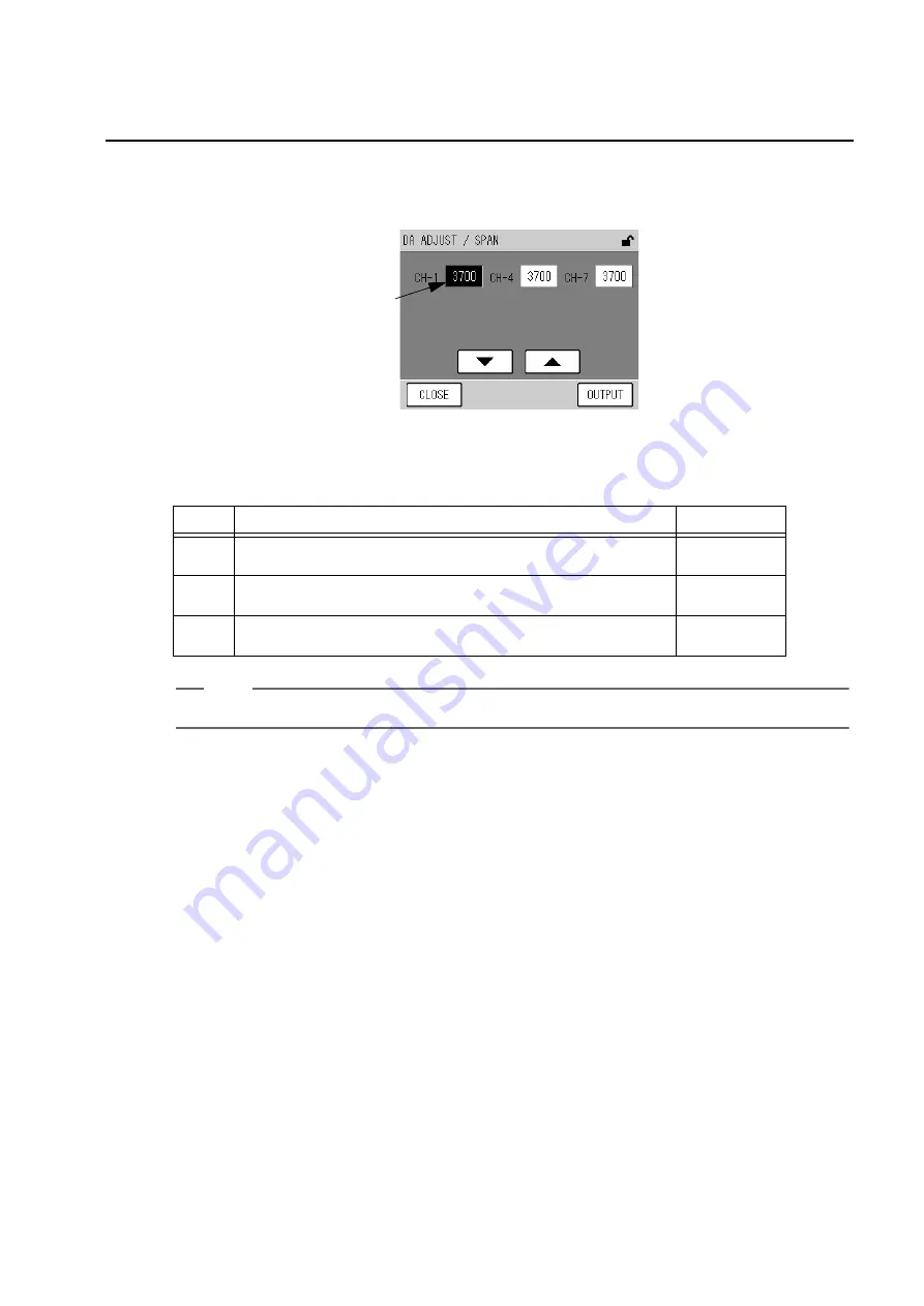
Span output adjustment

1.

Output [100%] on the ANALOG OUTPUT screen and then press the [SPAN] key.
The DA ADJUST/SPAN screen will be displayed.

Fig. 58  DA ADJUST/SPAN screen

The respective output point values of the channels are displayed. 
The outputs allocated to the channels are as follows:

Tip

For the terminal block output, see the rear panel signal table at the end of this document.

Press a point value button, and the button will be highlighted.
In this state, the following buttons allow you to perform the following operations.

The keys allow you to perform the following operations.

2.

Press the point value button for the channel to be adjusted. The selected point
value will be highlighted.

3.

Change the point value by pressing the [

] or [

] button.

4.

To establish all the point values, press the [OUTPUT] key.

5.

Press the [CLOSE] key to return to the ANALOG OUTPUT screen (Fig. 56 on page
44
).

6.

Check the output (page 45). If necessary, repeat the above steps to make
readjustment.

Point value

CH

Analog output 

Terminal

CH-1

Non-insulated output of momentary value (0 V to 1 V)
(ANALOG OUTPUT 1) 

C1 — C4

CH-4

Insulated output of momentary value (0 V to 1 V)
(ANALOG OUTPUT 2) 

A8 — A9

CH-7

Non-insulated output of rolling average value (0 V to 1 V) 
(ANALOG OUTPUT 2)

C5 — C8

[

]:

Increases the point value for the selected channel. A 10-point increment increases the
output about 3 mV.

[

]:

Decreases the point value for the selected channel. A 10-point decrement decreases
the output about 3 mV.

[CLOSE]: 

Returns to the ANALOG OUTPUT screen.

[OUTPUT]: 

Establishes each point value.

Summary of Contents for APMA-370

Page 1: ...Ambient CO monitor APMA 370 Operation Manual eng CODE GZ0000051249J...

Page 2: ...ributable to improper operation Any malfunction attributable to repair or modification by any person not authorized by HORIBA Ltd Any malfunction or damage attributable to the use in an environment no...

Page 3: ...one of the chemical symbols below In this case it satisfies the requirements of the Directive 2006 66 EC for the object chemical This product should not be disposed of as unsorted household waste You...

Page 4: ...igned to provide reasonable protection against harmful interference when the equipment is operated in a commercial environment This equipment generates uses and can radiate radio frequency energy and...

Page 5: ...esult in death or serious injury This is to be limited to the most extreme situations This indicates a potentially hazardous situation which if not avoided could result in death or serious injury This...

Page 6: ...ver Maintain ground to avoid electric shock Fire For your safety make sure to unplug the power plug from the electrical outlet when not in use Clear dust on the power plug periodically a few times a y...

Page 7: ...ted to this product Ambient CO Monitor APMA 370 Instruction Manual this manual This volume mainly discusses the operations for daily measurement and daily maintenance work of ambient CO monitor Ambien...

Page 8: ......

Page 9: ...screen 12 4 1 3 Screens for value setting 13 4 2 Preparation for Calibration 14 4 2 1 Entering the span gas concentration value 14 4 3 Automatic Calibration AIC 16 4 3 1 AIC setting 16 4 3 2 Precautio...

Page 10: ...Time adjustment 54 6 5 2 AIC setting 54 6 5 3 AIC sequence setting 54 6 5 4 Integration reset setting 55 6 5 5 Unit conversion factor 56 6 6 System Menu 58 6 6 1 LCD setting 58 6 6 2 Touch panel adjus...

Page 11: ...tact output 87 9 1 4 Alarm output 87 9 1 5 Analog output 87 9 1 6 Power shutoff output 87 10 APPENDIX 88 10 1 Measurement Principle 88 10 2 Specification 89 10 3 Unpacking 90 10 4 Installation 90 10 4...

Page 12: ......

Page 13: ...ue and rolling average or that of momentary value and average optional The default setting is the combination of momentary value and rolling average Addition of an RS 232C port optional will allow you...

Page 14: ...measured values alarms etc and touch keys for operation 3 RS 232C output port Used for maintenance and adjustments 4 Sample filter A filter for the sample line Replace this filter about every 2 weeks...

Page 15: ...6 mm O D 4mm I D Make sure that the sample gas pressure stays stable within 980 Pa In order to prevent condensation from occurring exercise caution to ensure that the sample piping is not exposed to...

Page 16: ...illuminated 3 hours later see 8 2 Alarm List page 80 to take action Since the end of warm up is not displayed it is recommended to warm up at night or in any other time zone when the operation is not...

Page 17: ...to disable the data logging capability before turning OFF the power so that the power is not turned OFF during access to the CF Turning OFF the power during access to the CF may damage the data in CF...

Page 18: ...equence zero span time 4 3 3 Setting the AIC sequence page 23 Output setting Set the analog output range Fixed Auto or External The default setting is Auto Select a desired mode in accordance with you...

Page 19: ...se of the standard specifications the MNT Maintenance signal is outputted when the maintenance switch is ON Fig 7 Mode icon 1 Icon display area 2 Current time 3 KEY LOCK icon button 4 Range display 5...

Page 20: ...In this state pressing this button displays the KEY LOCK screen Fig 93 on page 73 allowing you to lock unlock the keys Fig 10 KEY LOCK icon button When the keys are locked you cannot operate with the...

Page 21: ...played unit is different from the factory setting the range is changed to RX X The concentration ranges are named as 1 2 3 and so forth in the ascending order AUTO Displayed when the automatic range f...

Page 22: ...for line switching is used Active measurement line The currently selected measurement line is displayed ZERO The zero gas line is now being selected SPAN The span gas line is now being selected MEAS T...

Page 23: ...e are two methods available for the manual calibration one uses the calibration gas line and the other supplies the calibration gas to the measured gas line 4 1 Calibration related Screens This sectio...

Page 24: ...4 1 3 Screens for value setting page 13 4 Span calibration coefficient The entered span calibration coefficient is displayed Press the displayed span calibration coefficient the SPAN ADJUST screen wil...

Page 25: ...arest value in the settable range MEAS To use the MEAS line select this button SPAN To use the SPAN line select this button ZERO To use the ZERO line select this button EXTERNAL To use the external co...

Page 26: ...t line corresponding to the line to be used for the calibration For manual calibration using the calibration gas line SPAN For manual calibration using the measured gas line MEAS For auto calibration...

Page 27: ...ter a span gas concentration via the numeric keypad 6 Press the SET key to return to the CAL screen CANCEL Returns to the CAL screen without changing the settings CLEAR Deletes the value entered in th...

Page 28: ...ethod of AIC start Pressing the displayed AIC MODE setting will display the AIC MODE screen Fig 21 on page 18 START TIME Used to set the time for starting the next AIC sequence When the internal clock...

Page 29: ...will be displayed For the detailed explanation of each screen see AIC MODE page 18 to Automatic correction of start time page 22 5 On the setting screen change the settings and then press the SET key...

Page 30: ...Tip For the telemeter connection specifications to execute AIC using the internally set START TIME and INTERVAL automatically even if the start signal is not inputted because of telemeter malfunction...

Page 31: ...RT TIME of the next AIC the current START TIME INTERVAL If the calculated time does not meet the settable ranges of the LIMIT START END it will be corrected automatically see 4 3 2 Precautions in sett...

Page 32: ...Press the value to be changed The value will be highlighted allowing you to change it Using the and buttons change the value Note When you do not use the LIMIT START END function select the default va...

Page 33: ...the value to be changed The value will be highlighted allowing you to change it Using the and buttons change the value Note INTERVAL should be set to the AIC sequence time plus 10 minutes or longer If...

Page 34: ...he END time whichever is farther from the calculated time of the closest LIMIT START END to the calculated time Fig 25 Automatic correction of START TIME based on the LIMIT START END setting An exampl...

Page 35: ...ed The corresponding setting screen will be displayed WAIT or HOLD The following screen for time setting will appear Fig 29 A screen for time setting WAIT TIME Item Settable range Description WAIT 0 m...

Page 36: ...and the AIC sequence proceeds to the next step For example if WAIT for SPAN is set to 0 min no span gas will be supplied If CAL is set to NO calibration is not performed in the AIC sequence If the tot...

Page 37: ...sequence will start While the AIC sequence is in progress the CAL screen is displayed again and the AIC mode icon blinks Pressing the AIC key in this state displays the AIC abort message Fig 34 AIC a...

Page 38: ...ion gas line When using the measured gas line Reference page Gas line connection check Span value setting page 14 Measurement line switching MEAS ZERO Measurement line check MEAS page 27 Zero gas intr...

Page 39: ...SET key on the CAL screen is valid only when MODE is set to MEAS or ZERO 4 Press the YES button The zero calibration will be started After the calibration is completed the zero calibration coefficien...

Page 40: ...N SET key on the CAL screen is valid only when MODE is set to MEAS or SPAN 4 Press the YES button The span calibration will be started After the calibration is completed the span calibration coefficie...

Page 41: ...tion gas line display the MODE screen and change the measurement line to MEAS When using the measured gas line supply the sample gas to the measured gas line 2 Press the CLOSE key on the CAL screen Th...

Page 42: ...screen to display the MENU DATA screen and then press the button of the data to be displayed Fig 39 MENU DATA screen The buttons allow you to perform the following operations AVERAGE 1 to AVERAGE 3 Di...

Page 43: ...n an alarm occurred the alarm icon is displayed For the details of the alarm icon see Alarm icon Checking the data alarm status page 79 If no data is recorded the following message appears Fig 41 Mess...

Page 44: ...y Lock page 73 2 Display the data to be deleted on the screen for data check and press the DELETE key The message confirming data deletion will appear Fig 42 Message confirming data deletion 3 Press t...

Page 45: ...ime displayed on the AVERAGE screen is the final data acquisition time Pressing the AVERAGE 1 AVERAGE 2 or AVERAGE 3 on the MENU DATA screen displays the screen showing the latest data Fig 44 AVERAGE...

Page 46: ...ntegration or rolling average data is displayed no data will be recorded If the internal clock is put back The subsequent operation depends upon the corrected time If the corrected time is the same as...

Page 47: ...e automatically deleted The time displayed on the INTEGRATION screen is the final data acquisition time Pressing the INTEGRATION on the MENU DATA screen displays the screen showing the latest data Fig...

Page 48: ...nd then the integration value output will be reset to zero integration reset If the external integration reset is not performed after the time of the ongoing integration end the waiting time for integ...

Page 49: ...played on the ROLLING AVERAGE screen as time passes Fig 46 ROLLING AVERAGE screen For the screen functionalities see Screens for data check page 31 Rolling average calculation The momentary value at t...

Page 50: ...meter see page 49 Setting the analog output range see page 50 Setting the current time see page 54 Setting the AIC see page 16 Setting the AIC sequence see page 23 Selecting the integration reset see...

Page 51: ...re available DATA Fig 39 on page 30 HISTORY Fig 48 on page 40 MAINTENANCE Fig 55 on page 44 RANGE Fig 62 on page 50 SETTING Fig 67 on page 53 SYSTEM Fig 72 on page 58 COMMUNICATION Fig 82 on page 64 T...

Page 52: ...o perform the following operations Operation of the HISTORY screens The common functionalities to the HISTORY screens are described below On the MENU HISTORY screen press the button for the history to...

Page 53: ...eted A message will appear confirming the data deletion Fig 50 Message confirming data deletion 2 Press the YES button The message of deleting data will be displayed and the data deletion will start A...

Page 54: ...be displayed Fig 52 CAL ADJUSTMENT HISTORY screen For the screen functionalities see Operation of the HISTORY screens page 40 6 2 2 Alarm history Press the ALARM HISTORY button on the MENU HISTORY scr...

Page 55: ...ce If an alarm occurs within the AIC sequence period the alarm record is also displayed with the history data Data time differs depending on the status of AIC sequence Refer to Table 2 Data time Table...

Page 56: ...PUT 2 which varies depending on the specification integration value for the standard specifica tion are displayed as buttons Note All outputs are always in the MEAS mode the current measured value is...

Page 57: ...CLOSE key to return to the MENU MAINTENANCE screen Note Pressing the CLOSE key will put all the output back to the measured values CLOSE Returns to the MENU MAINTENANCE screen ZERO Displays the DA AD...

Page 58: ...be adjusted The selected point value will be highlighted 3 Change the point value by pressing the or button 4 To establish all the point values press the OUTPUT key 5 Press the CLOSE key to return to...

Page 59: ...cted point value will be highlighted 3 Change the point value by pressing the or button 4 To establish all the point values press the OUTPUT key 5 Press the CLOSE key to return to the ANALOG OUTPUT sc...

Page 60: ...E screen Displays the previous page Displays the next page Signal name Unit Description SIGNAL MAIN mV Voltage of the measured CO value SIGNAL COMP mV Voltage of the interference component value CELL...

Page 61: ...owing operations Changing the operating hours resetting 1 Press the button of the operating hour to be changed reset The HOUR METER screen for setting will be displayed Fig 61 HOUR METER screen for se...

Page 62: ...ANALOG OUTPUT RANGE screen will be displayed Fig 63 ANALOG OUTPUT RANGE screen ANALOG OUTPUT1 This screen shows the current range status of each analog output signal The currently used range type is...

Page 63: ...o be changed The RANGE screen will be displayed Fig 64 RANGE screen OUTPUT 1 The range is set by choosing a button of range setting The keys allow you to perform the following operations Tip Among the...

Page 64: ...LOG OUTPUT RANGE screens page 50 6 4 2 ANALOG OUTPUT 2 range rolling average Press the ANALOG OUTPUT 2 RANGE button on the MENU RANGE screen The ANALOG OUTPUT2 RANGE screen will be displayed Fig 66 AN...

Page 65: ...IME ADJUST Displays the TIME ADJUSTMENT screen Fig 68 on page 54 AIC Displays the AIC screen Fig 20 on page 16 AIC SEQUENCE Displays the AIC SEQUENCE screen Fig 28 on page 23 INT RESET Displays the IN...

Page 66: ...ing operations Note If you press the CANCEL key before completing the setting the time prior to the change will apply The time cannot be set on a second basis Pressing the SET key will automatically s...

Page 67: ...ror input contact is opened the integration reset is per formed with the internal clock Besides if AIC MODE is set to EXTERNAL see 4 3 1 AIC setting page 16 the AIC sequence will be started with the i...

Page 68: ...een shows the current concentration in a different unit and no setting on this screen affects the analog output and others The currently specified unit conversion factor is also displayed as a button...

Page 69: ...pad The keys allow you to perform the following operations 2 Enter a desired value via the numeric keypad 3 Press the SET key The factor will be changed and the UNIT CONVERSION FACTOR screen is displa...

Page 70: ...s a button To change the time setting press the button of the time for automatic backlight OFF see Setting the time for automatic backlight OFF page 59 The current brightness setting for the LCD is al...

Page 71: ...following operations 2 Press the button of the time to be set 3 Press the SET key The time setting for automatic backlight OFF will be changed and the LCD SETTING screen is displayed again Controllin...

Page 72: ...s If the positions deviate exceeding this limit the following steps cannot be performed Contact us Adjustment procedure 1 Press the TOUCH PANEL ADJUSTMENT button on the MENU SYSTEM screen The TOUCH PA...

Page 73: ...d in accordance with the message on the screen and then press the SET key If the entered password is correct a message will appear prompting you to enter a new password Note If the entered password is...

Page 74: ...a new password Enter a value via the numeric keypad The function of each key is the same as on the PASSWORD SETTING screen requiring the current password Fig 77 on page 61 4 Enter the new 4 character...

Page 75: ...ental power outage occurs data during a period of 10 minutes maximum may not be recorded 1 Press the SAVE button on the MENU SYSTEM screen The message confirming the saving of the data will appear Fig...

Page 76: ...s only displayed when Ethernet is enabled optional Fig 82 COMMUNICATION menu The buttons allow you to perform the following operations MACHINE ID SETTING Displays the MACHINE ID SETTING screen Fig 83...

Page 77: ...ID SETTING screen Immediately after this screen has been displayed the value for the currently set machine ID is displayed on the button Pressing the MACHINE ID button allows you to change that value...

Page 78: ...2 Use the numeric keypad to enter a desired value 3 Press the SET key You will return to the MACHINE ID SETTING screen At this stage the changed setting is not reflected For the reflection of the set...

Page 79: ...that the data is being saved After the data has been successfully written a message screen will be displayed prompting you to restart the APMA 370 Fig 85 Message screen showing that the data is being...

Page 80: ...ng buttons Pressing each IP ADDRESS button allows you to change the IP address see Changing the IP address page 69 Pressing each SUBNET MASK button allows you to change the subnet mask see Changing th...

Page 81: ...erations 2 Use the numeric keypad to enter a desired value 3 Press the SET key You will return to the TCP IP SETTING screen At this stage the changed setting is not reflected For the reflection of the...

Page 82: ...operations 2 Use the numeric keypad to enter a desired value 3 Press the SET key You will return to the TCP IP SETTING screen At this stage the changed setting is not reflected For the reflection of...

Page 83: ...lowing operations 2 Use the numeric keypad to enter a desired value 3 Press the SET key You will return to the TCP IP SETTING screen At this stage the changed setting is not reflected For the reflecti...

Page 84: ...the data is being saved After the data has been successfully written a message screen will be displayed prompting you to restart the APMA 370 Fig 91 Message screen showing that the data is being save...

Page 85: ...lighted When the keys are unlocked the KEY UNLOCK icon is highlighted The buttons allow you to perform the following operations KEY LOCK To lock the keys when the keys are unlocked press this button W...

Page 86: ...password and then press the SET key If the entered password is correct the requested action will occur If not correct no action will occur and the PASSWORD screen will be displayed again Tip The defa...

Page 87: ...E screen The current status of the maintenance switch is highlighted If the external switching is not selected the status of the maintenance switch can be changed by pressing the ON or OFF button The...

Page 88: ...onditions Replacement procedure 1 Push the PUSH marked area on the front panel door to open the door 2 Turn the filter cover leftward and then pull it out 3 Remove the filter packing and then replace...

Page 89: ...Specification Qty Part No Replacement period 1 Filter element PA 10L 54 mm in diameter 0 5 mm t 24 pieces per package 1 3200043947 2 weeks 2 O ring JISB2401 G70 FKM Teflon coated 1 3200043785 1 year...

Page 90: ...ou to check the current alarm When an alarm occurs the ALARM key will be displayed Pressing this key displays the ALARM screen Fig 98 ALARM screen The currently occurring alarms are listed One page ca...

Page 91: ...icon Alarms Reference Remarks Priority POWR Power ON page 80 Hidden on the ALARM screen high MNT Maintenance page 80 AIC AIC page 80 LINE Line page 80 BATT Battery page 80 CAL Calibration page 80 Hid...

Page 92: ...after line switching from ZERO or SPAN to MEAS This shows an operating status No remedial action is required BATT Battery The voltage of the battery for memory backup has decreased Note For replacing...

Page 93: ...ure sensor 3 error The atmospheric pressure sensor or sensor circuit fails Possible cause Remedial action Reference The measured value is not stable Perform the zero calibration again page 27 Any gas...

Page 94: ...perature deviates from the specified range 0 C to 40 C Allow the instrument to stand for a while in an environment of temperature within the specified ambient temperature range Possible cause Remedial...

Page 95: ...available For the CF related features refer to the Instruction Manual for APXX 370 Series Compact Flash Memory Possible cause Remedial action Reference There is a leak on the measured gas line or the...

Page 96: ...p is operating The connector is disconnected Connect it properly page 3 Possible cause Remedial action Reference The range not set improperly Set the range properly or select the automatic range page...

Page 97: ...ement Every 2 weeks page 76 Check the pump and diaphragm If they have been used exceeding their replacement time replace them Replacement period of the diaphragm Every year Replacement period of the p...

Page 98: ...nt momentary value range is output as follows 9 1 2 Contact input Note The inputs of the AIC start and integration reset do not respond to the changes occurring within less than 0 1 second The input o...

Page 99: ...MNT ZERO SPAN or Calibra tion error occurs The details of general error output vary depending upon the specifications See the list of general errors at the end of this document For information on eac...

Page 100: ...ell at a certain flow rate using a solenoid valve which is actuated at a frequency of 1 Hz Unless the gas concentration of the measured component is changed in the cell the output from the detector es...

Page 101: ...et Interference effect Moisture 25 C 80 0 3 ppm CO2 0 1 0 3 ppm Sample collection rate Approximately 1 5 L min Flow rate of calibration gas Approximately 2 5 L min Display Measured value alarm time al...

Page 102: ...magnetic field The dust level shall be 0 1 mg m3 or less There shall be no corrosive gas The relative humidity shall be 85 or lower The altitude shall be 3000 m or less A 3 pole power cable set shall...

Page 103: ...strument Fig 102 Mounting the APMA 370 on a 19 inch rack The following figure shows a cut panel and its screw positions Fig 103 Mounting the APMA 370 on a panel As illustrated place a supporting base...

Page 104: ...the analyzer 1 Remove the 8 screws on the cover and then open the cover Fig 104 Removing the cover 2 Remove the 2 fixing screws Fig 105 Fixing screws 3 Raise the spring holder and then put it over the...

Page 105: ...0 APPENDIX 93 10 5 Drawings External dimensions V3146280A GZ0000577849A Flow sheet V1016119A GZ9100352117A Rear panel signal table V1027816 GZ9100363253 A list of general errors V1027821A GZ9100363258...

Page 106: ......

Page 107: ...2 Miyanohigashi Kisshoin Minami ku Kyoto 601 8510 Japan http www horiba com...

Reviews: