background image

Excessive oil on the after cooler pipe or compressor

head usually indicates air leakage. Locate air leaks with

soap solution while the compressor is operating. 

While

the compressor is in the off cycle, check the unloaders
under pressure.

Excessive oil consumption is a difficult problem.

Before repair, take the following steps:

a. 

Confirm the 

Complaint-Oil at the tank drain does

not necessarily indicate 

high oil 

consumption.

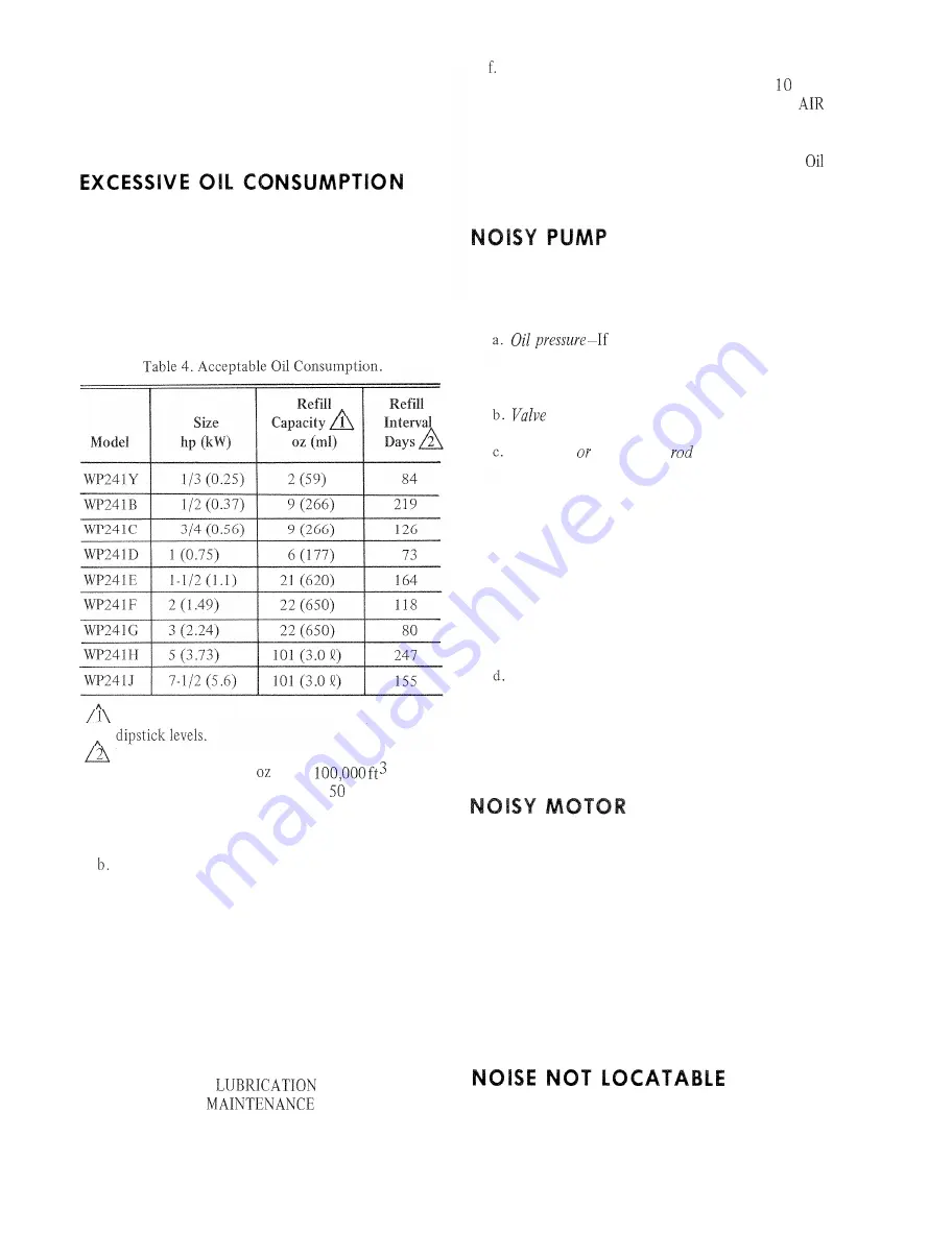
Table 4 shows acceptable oil consumption in terms
of fill amount and time between refills.

Oil capacity in crankcase between high and low

Days running time between high and low dipstick
levels, based on three   oil per 


 air used

(31 

ml 

oil per Ml air used) and 

 percent maxi-

mum duty cycle. Does not allow for spillage or
leakage.

 Make certain proper grade of nondetergent oil is

being used (see Table 2) and compressors are not
being overfilled. Overfilling always causes high oil
consumption. Oil level should never be above the
high mark on the dipstick.

c. Check for leaks.

d. Check intake filter/piping and crankcase breather

valve(s) for cleanliness and obstruction.

e. Check for excessive oil pressure or high percent

operation (see 

 and PRESSURE

paragraphs in 

 section). If, after

performing the above, a unit is still considered an
oil consumer with no apparent external cause, then:

 Check pump-up and cycle pressures against the

values in Table 3. Differences greater than   

per-

cent indicate worn parts (see WON’T PUMP 
paragraph).

g. Remove valves and examine piston top for oil. 

wetting is acceptable, but an accumulation of oil
indicates a defective pump.

The 

most common reason for a noisy pump is a loose

flywheel or motor pulley. Check for these first, then
check:


low, 

check pump as described in

WRONG 

OIL 

PRESSURE paragraph. 

Lack 

of oil

pressure may have caused bearing damage.

 assemblies 

-Make certain they are tight.

Wrist pin   connecting 

 bearings-Stop 

pump

and remove belts. Using the flywheel, rotate pump

back and forth about two inches (5 1 mm). If knock
is heard, a bad wrist pin or connecting rod bushing

probably exists. Inspect the rod bushings by
removing side plate and rod caps or 

remove 

head

and observe piston while rocking flywheel. Piston
should follow movement without play (except at
top and bottom dead center where piston appears
to hesitate). Inspect cylinder and head for carbon

build-up.

Bad main 

bearings-Check for end play by attempt-

ing to move flywheel in different directions. Listen
and feel for any play. End play on the crankshaft
is usually eliminated by removing one of the 

shims

beneath the bearing housing adjustment plate. A

slight drag, when turned by hand, is proper,

Check for a loose 

motor 

pulley. A low-pitch growl is

an indication 

of low voltage.

If noise is slight, lubricate motor in accordance with

instructions on nameplate. Noise should disappear so
motor runs properly. Watch for dry bearings, as 

these

shorten motor life. To check bearings, stop motor,
remove belt and check for side play in motor shaft. Turn
motor by hand. Any side play or noise is an indication

of bad bearings. If bearings are bad, replace motor. End

play (movement or motor shaft in and out) is common
in this type of motor and is not an indication of wear.

Use a large screwdriver or similar implement. Place

the point end against suspected areas and the other against
the ear. Listen for abnormalities.

75-7268

8

Summary of Contents for WP241 Series

Page 1: ...lLeaks 7 7 Excessive Oil Consumption 8 Noisy Pump 8 Noisy Motor 8 Noise Not Locatable 8 Chart 1 Motor Won t Start 9 Chart 2 Circuit Breaker Trips Fuse Opens 10 Chart 3 Won t Pump Air Runs but Tank Shows No Pressure Build Up 11 Chart 4 Won t Pump Air Builds Up Slowly or Not Complete 12 Chart S Won t Pump Air Pump Slows Stalls or Trips Circuit Breaker Fuse Opens 13 Excessive Vibration 13 REPAIR 14 P...

Page 2: ... 10 14 14 12 14 16 16 19 5 19 5 Motor Pulley Pitch Dia in 2 8 3 2 3 6 3 2 3 6 3 6 5 1 6 0 6 6 Safety Valve Receiver NPT 11 4 1 4 1 4 1 4 1 4 1 2 1 2 1 2 1 2 Crankcase Oil Capacity 4 oz 118 ml 28 oz 828 ml 28 oz 828 ml 22 oz 651 ml 48 oz 1 4l 2 qt 1 4l 2 qt 1 9l 6 qt 5 7l 6 qt 5 7l Lubrication System Splash Pressure Pump WP241Y 1 3 0 25 115 60 1 48 WP241B 1 2 0 37 208 60 3 60 3 56 WP241C 3 4 0 56 2...

Page 3: ...ng these items more often The three month checks will uncover any need for more frequent replacement LUBRICATION Quincy units use splash lubrication on the 1 3 to 3 4 hp 0 25 to 0 56 kW units and pressurized lubrication on 1 hp to 7 l 2 hp 0 75 to 5 6 kW units Stop both pumps remove and wipe off dipsticks reinsert dipsticks remove again and read If necessary add oil through dip stick port Use oil ...

Page 4: ...reading from the tank pressure The difference should not exceed 15 lb in2 100 kPa Allowing system pressure to drop to zero during replacement of element or gage tap installation will cause all actuators in the system to assume stem drawings for To change a filter in the 7 l 2 hp 5 6 k to Fig 1 Shut off air to filter at point A and bleed down housing by manually operating drain trap B Remove wing n...

Page 5: ...backup See wiring options shown in Fig 3 4 and S E T P S 2 5 10 lb in 35 70 kPd BELOW CUT IN PRESSURE 6278 1 Fig 4 Automatic Alternation with Automatic Backup For Single Phase Internally Protected Motors Ody F U S E S F U S E D DISCONNECT OR CIRCUIT BREAKER I I F SPiClFlED a 0 __ r PRESSURE SWITCHES 7 ji I I I i r M 2 1 I I Qs 3 C O M P I L 4 I TI I I L 2 I L L i C O M P MOTOR 2 STARTER 6277 l Fig...

Page 6: ...ck operation of each pump using manual switch over if necessary Record these figures for reference a card attached to the unit is handy Decreasing off periods with no change in pressure range indicate an increase in air consumption with an increasing pump up time This could be due to 75 7268 6 added devices or leaks Increasing pump up time with no change in pressure range or off time indicates wea...

Page 7: ...t around the threads during compressor s operation This indicates that oil pressure is reaching the system and the pressure gage s The pumps require oil pressure to operate intake valve unloaders and for lubri cation Lack of pumping ability indicates possible loss of oil pressure If oil appears at the threads of the gage and the oil pressure gage indicates no pressure replace the oil pressure gage...

Page 8: ...indicates a defective pump The most common reason for a noisy pump is a loose flywheel or motor pulley Check for these first then check Oil pressure If low check pump as described in WRONG OIL PRESSURE paragraph Lack of oil pressure may have caused bearing damage Valve assemblies Make certain they are tight Wrist pin OY connecting rod bearings Stop pump and remove belts Using the flywheel rotate p...

Page 9: ... 3 hp 0 37 and 0 25 kW a noise vibrating guard Check the belt guard by applying hand which cannot be traced to the pump is usually the check pressure to outside surfaces at different points CHART l MOTOR WON T START CHECK CIRCUIT BREAKER OR FUSE CHECK PRESSURE SWITCH TRACE WIRING TO FIND FAULT DISCONNECT POWER COOL MOTOR RECONNECT POWER NO R E P L A C E MOTOR c A REPLACE CAPACITOR STARTING SWITCH ...

Page 10: ... 0 1 YES S E E TROUBLESHOOTING CHART 5 Y E S S E E TROUBLESHOOTING 4 N O PROPERLY CHART 1 4 DISCONNECT POWER REINSTALL BELTS PLUG INTAKE BY HAND RECONNECT POWER S E E TROUBLESHOOTING t C H A R T 5 A Y E S GROWL IS LOW VOLTAGE CLUE I I034 75 7268 10 ...

Page 11: ...BUILD UP START 9 ISOLATE BUILDING Al R SUPPLY N O TURN UNIT ON REPLACE LOOK FOR AIR LEAK BETWEEN PUMP AND OUTLET VALVE j YES YES 4 DISASSEMBLE AND INSPECT VALVES c REPAIR AS NEEDED SEE PARTS LIST CRACKED DISCHARGE TUBE TANK OPEN VALVE ETC 11035 11 7 5 7268 ...

Page 12: ...VALVE CRACKED DISCHARGE TUBE TANK OPEN VALVE E TC ZIPPER LINE I I HM VALVES I SHUT OFF UNIT DISCONNECT COPPER LINE L REMOVE COVER BOLTS COVER TAP WITH BLUNT INSTRUMENT TO LOOSEN 1 SLOWLY DEPRESS PISTON TO FEEL RESISTANCE OF L RETURN SPRING AND PISTON CONTACTING VALVE REMOVE PISTON CUP AND CLEAN L UNDERNEATH N O NORMAL OPERATION N O IN INTAKE VALVES INSPECT PISTON TOP AND REPAI R AS NEEDED SEE PART...

Page 13: ...reduce vibration noise This problem is usually due to omission of vibration pads or an uneven weight distribution on the pads Shut unit off and apply weight to different corners of the unit Shim out excessive rocking Use adjustable levelers for uneven floors Belt guards often produce a vibrating noise even under Sometimes even normal operation of the compressor is considered excessive in noise or ...

Page 14: ...ecessary All others use a split hub and key Remove flywheel by removing hub bolts and nuts and driving a wedge into split NOTE When removing discharge tube connector from old pump loosely install the male coupling on the discharge tube in the connection to prevent collapse during removal OIL PUMP REPLACEMENT Remove pump intake filter and the unloader air supply line of 3 4 hp 0 56 kW and up If fly...

Page 15: ...or inside of wiring cover plate for proper connections for voltage being used and or rotation The compressor will pump air if rotated backwards but will not cool properly INTAKE AND EXHAUST VALVES UNLOADER Intake valves exhaust valves and unloader mechanisms can be disassembled for inspection cleaning or repair for all compressor sizes except the l 2 hp 0 37 kW The l 2 hp 0 37 kW unit has a head s...

Page 16: ... l 3 to 2 hp 0 25 to 1 5 kW units use a Honey well PP901 or PP902 PRV For detailed maintenance and repair information see Form No 75 2558 The prv station used on the 3 11 2 2 kW units is a combination of a Pall Trinity Micro Corp filter and a Norgren regulator and relief valve see Fig 15 and Table 3 To perform maintenance and repair work on the prv station shut off air supply from tank Bleed down ...

Page 17: ...t element kit for PI 901 PI 902 PRV is 14003121 001 See Form 75 2558 for other prv parts Fig 13 Honeywell Intake Filter Part No J 3895 4 See Fig 15 and Table 5 Table 5 7 l 2 HP Filter PRV Parts List Nomenclature 7 l 2 HP WP241 Refer all inquiries to Quincy Compressor Refer all inquiries to Quincy Compressor 17 75 7268 ...

Page 18: ...Il08 FFII210 EFIJ216 FFH230 FFII325 FFH340 FF11370 X2 Plain 106 Loadless 108 Loadiess 2 IO Loadlegs 2 16 Loadless 230 Loadless 325 Loadless 340 Loadless 370 Loadless l 3 0 5 l 2 0 37 3 4 0 56 1 0 75 l l 2 1 1 2 1 5 3 2 2 5 3 7 7 l 7 S 6 48 56 56 14x 145T 145T 182T 184T 71 y 1 I S 60 1 08 60 3 30 60 3 460 60 3 208 60 3 230 60 3 460 60 3 460 60 3 460 60 3 500 410 460 480 460 400 570 550 610 I A 44 I...

Page 19: ...ty Micro PARTS Local distributor or Pall Trinity Micro Corporation Cortland NY 13045 Supply exact part number NORGREN PARTS Local distributor or C A Norgren Company Littletown CO 80 120 Supply exact part number HONEYWELL PARTS Local Honeywell Serviceline Center Supply part number and compressor model number Mechanical devices must be serviced periodically if they are expected to give continued sat...

Page 20: ...OLUMBIA Ws h ngto D C McLean V A 703 8 2 7 3 7 0 5 FLORIDA Jackronv lle F L 904 3 9 6 6971 MONTANA Mlsrouia M T 406 7 2 8 7 4 4 2 Cincinnati OH 1513 9 4 8 4 1 8 5 Cleveland O H 216 361 7 3 7 3 TEXAS ALIst TX 512 4 7 8 1788 WYOMING Carper W Y 307 2 6 5 9 3 7 4 or 1 8 0 0 4 4 3 8 4 4 6 Oll Freei NEBRASKA O m a h a N8 4021331 3200 Colurnb s O H 16141 486 5971 X El P a s o T X I91 5 5 3 3 9 9 2 4 NEW ...

Reviews: