

WEB-8000 CONTROLLER
3
31-00091—02
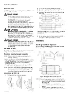
Wiring earth ground and power
WARNING
Before making power terminations, de-energize
the 24V power source.
Do not restore power until completing all other
mounting and wiring. See “Power up and initial
checkout” on page 4.
Prerequisite:
A nearby earth grounding point.
1.
Install the included earth ground wire to the control-
ler’s earth ground spade lug, and terminate the other
end to a nearby earth ground.
2.
Unplug the controller’s 2-position power connector
plug and terminate the 24V supply source (AC or DC)
to the connector. Leave connector unplugged for now.
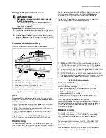
Communications wiring
Ports for field communications are shown below.
Fig. 4. Communications ports on controller.
WiFi
An integral WiFi adapter provides wireless connectivity
using the IEEE 802.11a/b/g/n standard, and provides an
RP-SMA coax antenna connector.
The WiFi configuration switch sets operation as follows:
• OFF - (Default, middle) WiFi adapter is disabled.
• ACC - Controller provides operation as a WiFi access
point for up to 20 clients.
• CLT - Controller operates as a client to an existing
802.11a/b/g/n router or access point.
Refer to the document
JACE-8000 WiFi Guide
for details
on WiFi configuration and factory-default IP settings.
RS485 wiring
On the controller’s top side, two RS485 ports operate as
COM1 and COM2. Each port is capable of up to 115,200
baud, and uses a 3-position, screw terminal connector.
Use shielded, twisted-pair, 18-22 AWG cabling to wire in a
continuous multidrop fashion to other RS485 devices:
“minus to minus”, “plus to plus,” and “shield to shield.”
Connect the shield wire to earth ground at one end only.
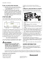
The following figure shows example wiring.
.
Fig. 5. RS485 wiring example.
RS485 BIAS SWITCHES
Each RS485 port has an adjacent 3-position biasing
switch, with these settings:
•
BIA
- (Default, middle) Controller provides RS485
biasing, but without a termination resistor.
•
END
- Both RS485 biasing and a termination resistor
are provided by the controller.
•
MID
- No RS485 biasing or termination resistor is
provided by the controller.
Often, adding RS-485 biasing can improve
communications by eliminating indeterminate idle states.
See the full
Mounting and Wiring Guide
for more details on
RS485 biasing. Each RS485 port has two LEDs. See
“Status LEDs,” page 4.
Ethernet wiring
Two RJ-45 10/100-Mbit Ethernet connectors are labeled
PRI (LAN1) for
primary
, and SEC (LAN2) for secondary.
Use a standard Ethernet patch cable to an Ethernet
switch.
The factory-default IP address for PRI is 192.168.1.140.
The default subnet mask is 255.255.255.0. By default, the
SEC (LAN2) port is disabled.
Refer to the
WEB-8000 Install and Startup Guide
for details
on the software configuration of the Ethernet ports.
1
RS485 ports and bias switches.
2
WiFi adapter, settings switch, and antenna.
3
Ethernet ports, 10/100-Mbit, RJ-45.
4
Earth ground and 24V power input.
M35800A
1
RS485 port A (COM1) is often used to support a trunk of
T-IO-16-485 modules. NOTE: Do not mix T-IO-16-485s
with other types of RS485 devices on the same RS485 trunk.
2
RS485 port B (COM2) supporting a network of other field
devices using RS485 communications.
3
(NOTE): RS485 devices on the same network should use
the same protocol and baud rate. Up to 32 or more devices
may be supported, depending on device specifications.
M35801