WEB-8000 CONTROLLER
Automation and Control Solutions
Honeywell International Inc.
1985 Douglas Drive North
Golden Valley, MN 55422
customer.honeywell.com
® U.S. Registered Trademark
© 2016 Honeywell International Inc.
31-00091—02 M.S. Rev. 02-16
Printed in United States
By using this Honeywell literature, you agree that Honeywell will have no liability for any damages arising out of your use or
modification to, the literature. You will defend and indemnify Honeywell, its affiliates and subsidiaries, from and against any
liability, cost, or damages, including attorneys’ fees, arising out of, or resulting from, any modification to the literature by you.
Power up and initial checkout
1.
Apply power. To do this, do
one
of the following:
• Insert the 2-position 24V power connector plug,
or
• Insert the barrel plug of the wall-mount AC
adapter (WPM-8000).
2.
Check the STAT (Status) and BEAT (Heartbeat)
LEDs. When power is applied, the green “STAT” LED
will light. This indicates the system is OK, with power
applied. During bootup, the “BEAT” LED may blink at
1 Hz with a 90%/10% on/off duty cycle. When boo-
tup completes, the platform daemon is started, and
the normal 1 Hz flash at 50%/50% on/off duty cycle
of the “BEAT” LED returns.
STATUS LEDS
The controller provides a number of status LEDs, with all
but one visible with the front access door closed. See Fig. 6.
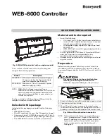
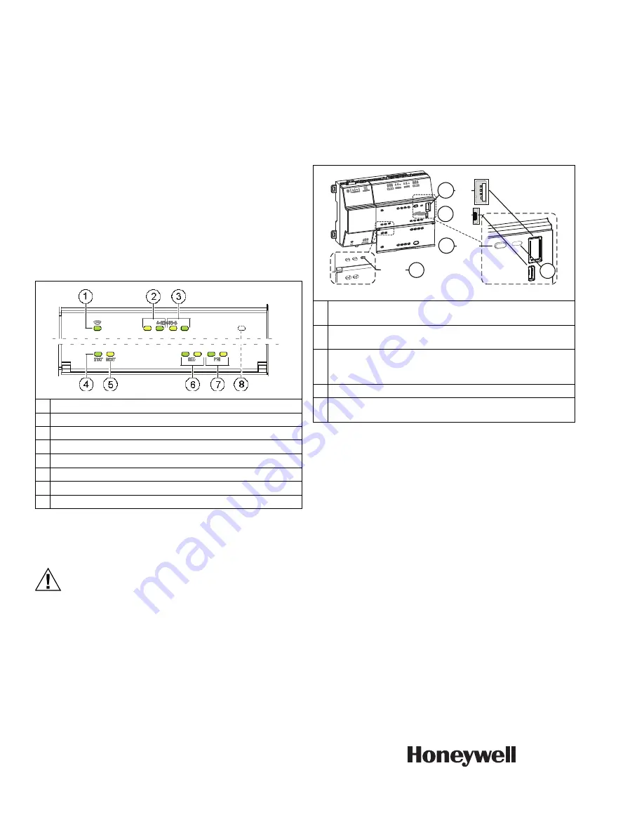
Fig. 6. LEDs and brief descriptions.
If the “BEAT” LED stays on constantly, does not light, or blinks
very fast, contact System Engineering for technical support.
CAUTION
The 1Hz, 90%/10% on/off “BEAT” flash at
bootup also occurs during other critical
operations, such as a firmware upgrade to the
controller and/or any attached modules.
To be safe, do not remove power from the controller
while its “BEAT” LED flashes with a 90%/10% on/
off duty cycle. Wait for the normal (50%/50%)
flash to return before removing power.
For details on the controller’s various LEDs and
pushbutton switches, see the full
Mounting and Wiring
Guide
.
USB ports and pushbutton switches
Behind the controller’s front access door are two USB
ports, two pushbutton switches, and an associated LED.
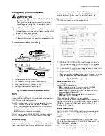
Fig. 7. USB ports and switches behind access door.
The DEBUG port is a standard Micro-A type USB port for
serial debug communications to the controller. Use a
serial terminal program (for example: PuTTY) to access the
controller’s “system shell” menu. This provides access to a
few basic platform settings.
Default DEBUG port settings are: 115200, 8, N, 1
(baud rate, data bits, parity, stop bits). For details on using
a serial connection to the DEBUG port, see the JACE-8000
Install and Startup Guide and JACE-8000 Mounting and
Wiring Guide.
NOTE:
Login requires admin-level platform credentials.
MORE INFORMATION
Additional controller hardware details are in the JACE-
8000 Mounting and Wiring Guide, including option
module capacity considerations, RS485 biasing details,
and status LED details.
1
WiFi (Green) - Lit whenever WiFi config switch is not Off.
2
RS485 “A” (COM1): Transmit (TX) and Receive (RX).
3
RS485 “B” (COM2): Transmit (TX) and Receive (RX).
4
STAT (Green) - Remains lit while controller is powered.
5
BEAT (Yellow) - “Heartbeat”, normally 1Hz, 50% duty cycle.
6
Secondary Ethernet, SEC (LAN2) “Link” and “Activity”.
7
Primary Ethernet SEC (LAN1) “Link” and “Activity”.
8
(Behind Door) BACKUP - Green, typically Off.
MCR35802
1
PROG - USB 2.0 for usage with USB flash (thumb)
drive.
2
DEBUG - Micro-A USB for serial debug
communications.
3
BACKUP - Pushbutton switch to start a USB backup, or
if held in during power up/boot up, a factory recovery
image.
4
SHT/DWN - Recessed switch for controlled shutdown.
5
BACKUP - LED to indicate USB media present, or a
backup, restore, or factory recovery image in progress.
M35803A
3
5
4
2
1
BACKUP
DEBG
PROG
BACKUP
SHT/DWN