

EN1R--9137 9808R6--NE
5
Ensure combustion chamber is free of gas before
start up.
Conduct a thorough check out when installation is
completed.
At the first start the ignition controller can be in lock
out; depress reset button to free control.
Tightness test after installation
·
Apply an approved liquid leak detector to all pipe
connections.
·
Start the appliance and check for bubbles. If a leak is
found in a pipe connection, remake the joint.
A gasket leak can usually be stopped by tightening the
mounting screws. Otherwise, replace the gasket.
·
Be careful not to clog bleed vent parts with liquid leak
detector residue.
Remember bleed vents will discharge air during gas valve
opening or closing giving false indication of leakage.
CAUTION
Keep liquid leak detector away from electrical connec-
tions.
ADJUSTMENTS
WARNING
Adjustments must be made by qualified persons only.
If the appliance manufacturer supplies checkout and/
or service and maintenance instructions carefully
follow them.
If such instructions are not provided then use the
procedure outlined below.
Pressure tap
The combination gas control is provided with a pressure tap of
9 mm O.D. at inlet and outlet side.
The gas/air module is provided with pressure taps of 9 mm
outer diameter to measure the high and the low air pressure.
The air pressure difference measured on the pressure taps of
the module is reduced with the same factor as the
amplification factor is reduced compared with the actual air
pressure difference.
When checking the pressure undo the screw a half turn and
slip tube over nipple.
Ensure that screw is retightened after making test.
CAUTION
To ensure a safe closing of the valves, it is essential
that voltage over the terminals of electric operators is
reduced to 0 Volt.
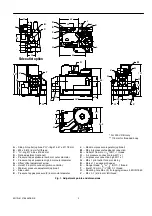
Offset adjustment on CO
2
% (see fig. 1)
·
Remove cap screw with a screw driver to expose offset
adjustment screw.
·
Check gas supply pressure to the appliance using a
pressure gauge connected to the inlet pressure tap.
·
Start fan and check air flow.
·
Energize both electric operators in order to have gas input
to burner and ignite boiler.
·
Adjust CO
2
% at the desired value at low output with offset
adjustment screw. Turn offset adjustment screw counter
clockwise to increase CO
2
%.
·
Replace cap screw and tighten pressure taps.
Offset adjustment on outlet pressure
·
Remove cap screw with a screw driver to expose offset
adjustment screw.
·
Check gas supply pressure to the appliance using a
pressure gauge connected to the inlet pressure tap.
·
Control the fan to produce the air pressure difference
stated by the boiler manufacturer.
·
Energize both electric operators in order to have gas input
to burner and ignite boiler. The main burner should ignite
within 3 seconds.
IMPORTANT
Adjustments must be made in the final mounting
position to avoid shift caused by weigth of the
diaphragm
·
Because of amplification factor tolerance, it is advisable to
adjust the offset at low outlet pressures. Turn offset
adjustment screw counter clockwise to increase or
clockwise to decrease outlet pressure.
·
Replace cap screw and tighten pressure taps.
Maximum outlet pressure adjustment (depending on combination gas
control) See fig. 1
The maximium outlet pressure is an optional feature, which
can only be used in atmospheric burner applications.
The maximum outlet pressure adjustment is used to limit the
load supplied to the main burner
·
Remove cap screw with a screw driver to expose offset
adjustment screw.
·
Determine the value to which the maximum outlet pressure
is to be set. Adjustments must be made when the main
burner is burning and the fan is in the maximum air flow
position.
·
Turn the maximum outlet pressure adjustment screw
slowly until the desired pressure is obtained.
Turn adjustment screw clockwise to increase or counter
clockwise to decrease outlet pressure.
·
Replace cap screw and tighten pressure taps.
CHECKOUT
After any adjustment check pressure taps and gas connec-
tions with an approved leak detection fluid for gas leakage.
After any adjustment set appliance in operation and observe
several complete cycles to ensure that all burner components
function correctly.
MAINTENANCE AND SERVICE
Under normal circumstances no maintenance or service is
required.
WARNING
Screws on the valve that have been sealed must
never be removed.