
EN1R--9137 9808R6--NE
2
K
62
45
84
37
13
24
24
12
96
42
85
17
105**
38
18
22
101
80.8
37
8
30
25
A
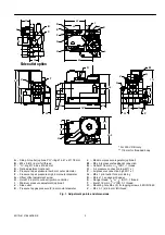
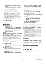
-- Side pilot outlet (optional) ”O”--ring Ø 4.47 x Ø 1.78 mm
B
-- M5 x 0.8 (3) 6 mm full thread
C
-- ”O”--ring Ø 15.55 x Ø 2.62 mm
D
-- Ratio adjustment (optional)
E
-- Pressure tap air pressure low 9 mm outer diameter
F
-- Pressure tap air pressure High 9 mm outer diameter
G
-- Offset offset adjustment screw
H
-- Hole Ø 2.6 mm to connect ignition controller
I
-- Minimum pressure adjustment (optional)
J
-- Side outlet
K
-- Pressure tap gas pressure (2) 9 mm outer diameter
L
-- Maximum pressure regulator (optional)
M
-- M5 x 0.8 pressure feedback connection
N
-- Outlet Ø 18 mm or
1
/
2
” ISO 7--1 thread
O
-- Air pressure connection low M11 x 1
P
-- Air pressure connection high M11 x 1
Q
-- M8 x 1 pilot outlet for 4 mm tubing
R
-- Molex 1.1 square pin header
S
-- Flange thread
3
/
8
” or
1
/
2
” ISO 7--1 thread
T
-- Inlet Ø 18 mm or
1
/
2
” ISO 7--1 thread
U
-- Mounting hole M5 x (2) for tapping screws 3.9 DIN 7990
V
-- M4 x 0.7 (4) 6.5 mm full thread
A
C
B
D
E
F
G
H
J
L
O
Q
P
R
S
T
U
I
M
N
Fig. 1. Adjustment points and dimensions
* For 220 V DBI only
V
V
24
24
29
98*
** 115 mm for threaded body
Side outlet option