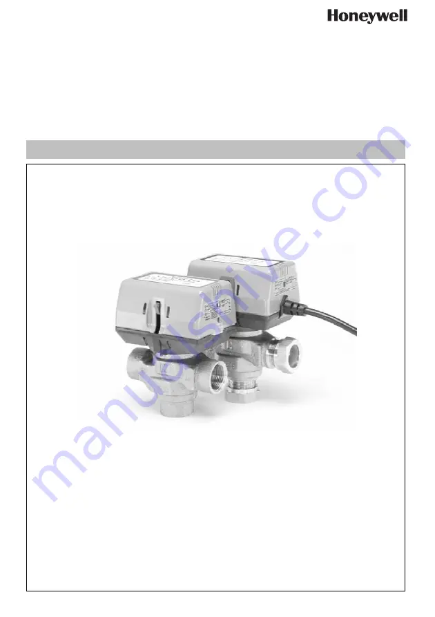
VC Series
Installation instruction • Einbauanleitung
Keep instructions for later use!Anleitung zum späteren Gebrauch aufbewahren!
3-Way Zone Valves
3-Wege Zonenventile
MU1H-28
06GE25 R01
07
Page 1: ...VC Series Installation instruction Einbauanleitung Keep instructions for later use Anleitung zum späteren Gebrauch aufbewahren 3 Way Zone Valves 3 Wege Zonenventile MU1H 2806GE25 R0107 ...
Page 2: ...ell com GB 1 Application 4 2 Specifications 4 3 Manual Opener 5 4 Installation 5 5 Wiring 6 6 Checkout and service 7 D 1 Anwendungsbereich 8 2 Spezifikationen 8 3 Handöffner 9 4 Einbau 9 5 Verdrahtung 10 6 Probebetrieb und Wartung 11 ...
Page 3: ...suse of its product Voltage 230V 50 60Hz standard models 24V 50 60Hz models are available on request Power Consumption 6 Watts Max at nominal Voltage during valve position change Use 24 V class 2 transformer Provide 6 VA for transformer and connection wire size Maximum duty Cycle 15 End switch rating 2 2 A inductive from 5 to 110 Vac 1 0 A inductive above 110 to 277 Vac Min DC switching capability...
Page 4: ...ly latched to the valve To remove Fig 4 press up on the latch mecha nism 1 located directly below the white manual open lever with thumb Simultaneously press the actuator down towards the body with moderate hand force and turn the actuator counter clockwise by 1 8 turn 45 degrees Lift actuator off the valve body 3 The valve may be installed with flow from A to B or B to A Fig 2 The valve body may ...
Page 5: ...f the Port A opening stroke On Molex connector models valve auxiliary switch voltage must be the same to meet approval require ment Fig 3 Valve mounting position Fig 4 Removing the actuator Fig 5 Valve mounting Fig 6 The manual opener X A B Manual opener WARNING Electrical installation cables and related accessories must comply with local laws directives and competent authorities Table 1 Electrica...
Page 6: ...one thermostat above room temperature to initiate a call for heat White valve position lever should move 2 For auxiliary switch models observe all control devices The valve should open and the auxiliary switch if present should close and make at the end of the opening stroke to activate auxiliary equip ment 3 Lower the set point of the zone thermostat below room temperature 4 Observe the control d...
Page 7: ...en die durch falsche Verwendung oder Zweckentfremdung seiner Produkte entstehen Spannung 230V 50 60Hz Standardmodelle Modelle mit 24V 50 60Hz sind auf Anfrage erhältlich Leistungsaufnahme Max 6 Watt bei Nennspannung bei Wechsel der Ventilspannung Transformator 24 V Klasse 2 verwenden 6 VA für Transformator und Anschlusskabelgröße vorsehen Maximales Schaltverhältnis 15 Endschalterbelastung 2 2 A in...
Page 8: ... Der entsprechende Hebel befindet sich direkt unterhalb des Hebels zur Handöffnung Gleichzeitig muss das Stellglied mit moderater Kraft nach unten auf den Ventilkörper gedrückt und im entgegengesetzten Uhrzeigersinn um 1 8 gedreht werden 45 Grad Dann kann das Stellglied vom Ventilkörper abgehoben werden 3 Das Ventil kann mit der Flussrichtung A nach B oder B nach A eingebaut werden Abb 2 Der Venti...
Page 9: ...Anschluss muss die Spannung an Ventil und Hilfsschalter identisch sein um die Zulas sung zu erhalten Fig 3 Lage des Ventils Fig 4 Entfernung des Stellglieds Fig 5 Einbau des Ventils Fig 6 Manuelle Öffnung X A B Manual opener WARNUNG Elektrische Installationen Kabel und Zu satzbauteile müssen örtlichen Gesetzen Richtlinien und behördlichen Vorschriften entsprechen Table 1 Elektrische Anschlüsse Far...
Page 10: ...bewegen 2 Bei Modellen mit Hilfsschalter müssen alle Regelein richtungen beobachtet werden Das Ventil sollte sich öffenen und der Hilfsschalter wenn vorhanden sollte sich am Ende des Öffnungsvorgangs schließen um die Hilfseinrichtungen zu aktivieren 3 Stellen Sie den Sollwert des Zonenthermostats auf einen Wert unterhalb der Raumtemperatur 4 Beobachten Sie die Regeleinrichtungen Anschluss A sollte...