Installation Instruction VARIODYN
®
D1 System
68
FB 798663.GB0 / 05.19
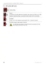
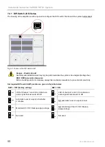
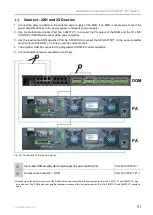
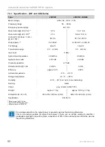
7.4.6 DIP switch 4XD300/4XD500
Before commissioning, the DIP switch
5
should be set to the desired function according to the table below. Here,
ON corresponds to the upper position and OFF to the lower one.
•
Disconnect the amplifier from the power source before setting the DIP switch
5
.
•
Set the DIP switch using a non-metallic tool.
•
The DIP switch positions are read in when booting up the amplifier.
ON
1
2
3 4
5 6
OFF
- 20 dB
CH 1
2
3
4
DC
FAULT
LOOP
SHORT DETECT
- 6 dB
ON:
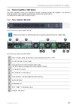
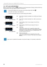
Signal LED 'sensitivity' illuminates from -20 dB for each channel
CH 1…4.
OFF: Signal LED 'sensitivity' illuminates from -6 dB for each channel
CH 1…4.
ON
1 2 3 4 5 6
OFF
- 20 dB
CH 1
2
3
4
DC
FAULT
LOOP
SHORT DETECT
- 6 dB
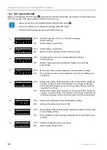
ON:
Faults relating to the 24 V power supply (AC and DC) are
displayed.
OFF: Faults relating to the 230 V power supply (AC only) are
displayed.
ON
1 2 3 4 5 6
OFF
- 20 dB
CH 1
2
3
4
DC
FAULT
LOOP
SHORT DETECT
- 6 dB
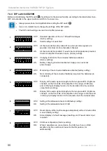
ON:
Loop mode
In the event of a short-circuit, the amplifier switches off for
approximately 0.75 seconds before restarting again immediately
at full power. This means the loop is fully available again more
quickly following a short-circuit.
OFF: Normal mode/spur line
In the event of a short-circuit, the amplifier switches off for
approx. five seconds. The power is then slowly increased again
after this.
Loop mode is only permitted for operation using loop technology incl. loop isolator modules (LIM).

