Installation Instruction VARIODYN
®
D1 System
42
FB 798663.GB0 / 05.19
Main Switch Unit (MSU)
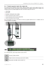
The Main Switch Unit (Part No. 583371.21) is used to individually safeguard the power supply of all VARIODYN
®
D1 components that are installed in a floor type cabinet. Up to three components can be connected to a MSU.
Each of the three connections can accept a current of max. 18 A. The overcurrent switch (per connection) is
automatically triggered if there is an overcurrent, but can also be used for manually switching the 230 V AC rated
voltage. If a supply voltage is present and the fuse is switched on, the respective indicator light will light up in
green.
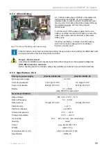
2
1
3
4
5
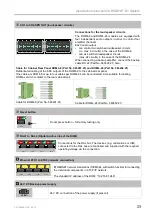
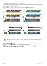
Fig. 35: Front view of main switch unit (MSU)
Additional information on the indicators refer to operating instructions (Part No. 798662.GB0).
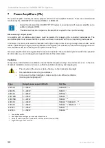
1
2
3
4
5
6
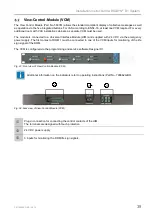
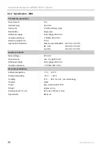
Fig. 36: Rear view of main switch unit (MSU)
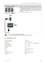
Connection of the individual (max. 3) power supply phases L1 / L2 and L3.
Maximum cable cross-section of 4 mm² (flexible) to 6 mm² (rigid).
The protective earthing conductor (PE) and neutral conductor (N) must always be connected.
/
/
Up to 4 components can be connected to terminals 2, 3 and 4, in accordance with the
requirements. These terminals can be single switched as a single pole with the fuses arranged
on the front.
Potential-free switch contacts for activating external devices for the remote display of the
switching status of the corresponding overcurrent circuit breaker.
Max. cable cross-section 2.5 mm²
RJ45 socket
Ethernet connection to DOM
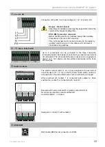
The rear-side Ethernet connection is connected to the front-side Ethernet connection (for direct
connection of the service PC on the front side of the MSU).
•
Neutral conductor
–
As a rule, it must be ensured that the neutral conductor is properly connected.
–
In particular, for three-phase connected devices in VARIODYN
®
D1 cabinet systems, suitable
protection must be provided against overvoltage caused by a break in the neutral conductor
and the phase shift which may result from this.
–
For single-phase connected devices, suitable protection against overcurrent must be ensured
to guard against the consequences of a break in the neutral conductor (usually caused by
the operator).
•
Observe permitted torque (max. 0.4 Nm) of the terminals!


