U2 COMBINATION VIEWING HEAD AND SIGNAL PROCESSORS
66-2071—02
4
NOTE: If the fault and flame contacts are wired to 220 VAC voltage and cable runs are long, it may be necessary to use
isolating/interposing relays to reduce induced noise.
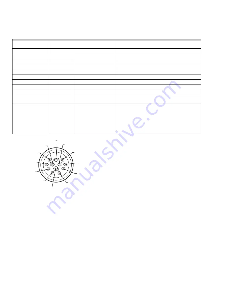
Table 3. U2 Wires and their function.
Fig. 1. Connector Pinout.
NOTES:
—
It is recommended to use shielded pairs of cable.
However, any cable can be used as long as ana-
log output and communication cables are individ-
ually shielded. Honeywell offers C12S cable with
12 conductors for use with the U2.
—
18 AWG is recommended
—
Wiring must be in conduit or tray as permitted by
code. Hazardous location wiring must meet area
classifications.
Mounting and Sighting
Mounting is 1 in. NPT (F). Refer to Fig. 7 for suggested U2
mounting. Before beginning the actual installation, determine
the best location for mounting the viewing head based upon
the following factors:
Pressure
The U2 lens will withstand 500 psi. If the U2 will be exposed to
pressures over 500 psi, contact your distributor or Honeywell
for guidance.
Temperature
The U2 can withstand an ambient temperature of 158 ºF
(70 ºC). The case temperature of the housing must not
exceed 158 ºF (70 ºC). Purge air will help reduce conducted
heat through the sight pipe and flange. A heat insulating Ultem
locking coupler adapter (R-518-PT12, R-518-PT12L) is
required and will reduce the conducted heat, however, direct
radiation can cause the housing case temperature to exceed
limits. If the ambient heat (direct radiation) is excessive, then a
fiber optic extension should be considered. The extension
uses a fiber optic cable assembly between the sight pipe and
the U2, allowing the U2 to be placed further away from the
heat source. Refer to the Fiber Optic Manual 69-2683 or
contact your distributor or Honeywell for assistance with fiber
optic selection and pricing.
The U2 models also have an internal sensor for measuring
temperature. To access the temperature reading at the U2,
refer to Fig. 2.
Purge Air
The U2 does not have a purge air connection directly on it, so
purge air must be provided via the mounting method. Refer to
the ACCESSORIES section and Fig. 7 for suggested U2
mounting. Purge air is used to prevent very hot gases from
reaching the U2 by continuously blowing cooler air through the
sight pipe. Air required is about 0.13 Nm
3
/min (5 SCFM)
delivered at 25 mm (1 in.) above the maximum back pressure
as measured at the “Y” or “T” section of the purge air
Pipe Fitting
Connection (CAB19)
Connector
(CAB22)
Function
Comments
Drain wire
Shield
Cable shielding
Tie to ground (black)
Black
Yellow/Green
Ground
Power ground
Red
Black #10
Power
Connect to 22-26 VDC
Green
Yellow #3
Relay common
Common for both flame and self check relays
Yellow
Yellow #4
Self check relay
Normally open contact
Grey
Yellow #2
Flame relay
Normally open contact
Brown
Yellow
- RS 485 communication
Modbus Connection
White
White
+ RS 485 communication
Modbus Connection
Blue
Black #7
Future use
Future use
Orange
Black #8
Current output
0-20 or 4-20 mA output corresponding to flame count. Use
ground as return line.
Purple
Black #9
File select
Grounded = parameter file 0
+24V = parameter file 1
NOTE: The file input wire should not be left uncon-
nected or in an unknown state. If not being
used or if using the default file 0, connect the
file input wire to ground.
M33313
NOT USED
YELLOW
YELLOW 2
YELLOW 3
YELLOW 4
YELLOW/GREEN
SHIELD
WHITE
BLACK 10
BLACK 9
BLACK 8
BLACK 7


