
HMR3500
4 www.honeywell.com
MOUNTING CONSIDERATIONS
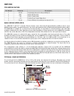
The following is the recommend printed circuit board (PCB) footprint for the HMR3500. The reference direction (forward)
is the right PCB assembly edge shown in Figure 1. Left to right, the interface connector is numbered pin 1 to pin 5 per the
pin configuration table.
UNC 4-40 fastening hardware is recommended for mounting the printed circuit board with at least 0.125 inch nylon
spacers to stand off the board from the mounting surface. Fastener hardware must be non-ferrous for full compass
performance with brass or nylon screws the usual materials of choice.
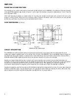
CASE DIMENSIONS
(in inches)
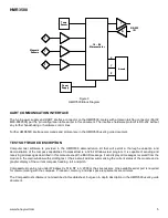
CIRCUIT DESCRIPTION
The HMR3500 circuit design starts with a microprocessor powered by power supply sub-circuit that takes the input
voltage and creates regulated power for the various other circuits in the HMR3500. Two 2-axis MEMS accelerometers are
mounted horizontally and vertically to combine into a 3-axis tilt sensing sub-circuit. Each accelerometer outputs a Pulse-
Width-Modulated (PWM) digital signal that the microprocessor measures for pitch and roll angles.
Besides an integral temperature sensor, a 2-axis and 1-axis magnetic sensor devices are mounted horizontally and
vertically to create a 3-axis measurement of the incident magnetic field upon the sensors. Each sensor output is amplified
and sent to a multiplexed input ADC residing inside the microprocessor. After digitizing, the magnetic signals are
corrected for hard and soft-iron magnetic errors created by the environment to which the compass is attached.
Heading computation uses the magnetic and tilt information inputs after compensation for errors. From the basic magnetic
heading, a declination value may be added to arrive at a geographic north referenced heading. An index offset value may
also be added to correct for mechanical installation misalignment on the target platform.
Figure 2
HMR3500 Case Dimensions