


3
69-0838
Do not locate the gas control where it can be affected by
steam cleaning, high humidity, dripping water, corrosive
chemicals, dust or grease accumulation, or excessive heat.
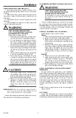
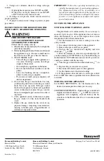
Fig. 1—Install flange to gas control.
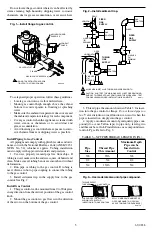
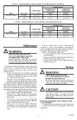
Fig. 2—Install sediment trap.
3. Thread pipe the amount shown in Table 3 for inser-
tion into the gas control or flange.
Do not thread pipe too
far.
Valve distortion or malfunction can result when the
pipe is inserted too deeply into the gas control.
4. Apply a moderate amount of good quality pipe com-
pound (do
not
use Teflon tape) to pipe only, leaving two
end threads bare. On LP installations, use compound resis-
tant to LP gas. Refer to Fig. 3.
TABLE 3—NPT PIPE THREAD LENGTH IN (IN.).
Pipe
Size
Thread Pipe
This Amount
Maximum Depth
Pipe can be
Inserted into
Control
3/8
9/16
3/8
1/2
3/4
1/2
3/4
13/16
3/4
GAS
CONTROL
GAS
CONTROL
HORIZONTAL
DROP
PIPED
GAS
SUPPLY
PIPED
GAS
SUPPLY
3 INCHES
[76]
MINIMUM
3 INCHES
[76]
MINIMUM
RISER
GAS
CONTROL
TUBING
GAS
SUPPLY
HORIZONTAL
DROP
3 INCHES
[76]
MINIMUM
RISER
M3077
2
1
2
2
1
2
ALL BENDS IN METALLIC TUBING SHOULD BE SMOOTH.
CAUTION: SHUT OFF THE MAIN GAS SUPPLY BEFORE REMOVING
END CAP TO PREVENT GAS FROM FILLING THE WORK AREA. TEST
FOR GAS LEAKAGE WHEN INSTALLATION IS COMPLETE.
M3098A
VALVE OUTLET
FLANGE
9/64 INCH HEX SCREWS (4)
1
DO NOT OVERTIGHTEN SCREWS.
TIGHTEN TO 25 INCH POUNDS.
1
6/32 INCH ROUND
SCREWS (1)
CONDUIT
COVER
To safeguard proper operation, follow these guidelines:
• Locate gas control in a well-ventilated area.
• Mount gas control high enough above the cabinet
bottom to avoid exposure to flooding or splashing
water.
• Make sure the ambient temperature does not exceed
the ambient temperature ratings for each component.
• Cover gas control when the appliance is cleaned with
water, steam, or chemicals or to avoid dust and
grease accumulation.
• Avoid locating gas control where exposure to corro-
sive chemical fumes or dripping water is possible.
Install Piping to Gas Control
All piping must comply with applicable codes and ordi-
nances or with the National Fuel Gas Code (ANSI Z223.1
NFPA No. 54), whichever applies. Tubing installation
must comply with approved standards and practices.
1. Use new, properly reamed pipe free from chips. If
tubing is used, make sure the ends are square, deburred and
clean. Make sure all tubing bends are smooth and without
deformation.
2. Run pipe or tubing to the gas control. If tubing is
used, obtain a tube-to-pipe coupling to connect the tubing
to the gas control.
3. Install sediment trap in the supply line to the gas
control. See Fig. 2.
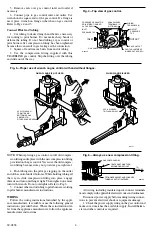
Install Gas Control
1. This gas control can be mounted from 0 to 90 degrees
in any direction from the vertical position of the gas control
knob.
2. Mount the gas control so gas flow is in the direction
of the arrow on the bottom of the gas control.
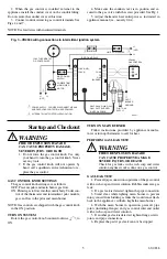
Fig. 3—Use moderate amount of pipe compound.
TWO IMPERFECT
THREADS
GAS CONTROL
THREAD PIPE THE AMOUNT
SHOWN IN TABLE FOR
INSERTION INTO GAS CONTROL
APPLY A MODERATE AMOUNT OF
PIPE COMPOUND TO PIPE ONLY
(LEAVE TWO END THREADS BARE).
M3075A
PIPE


