


69-0838
2
Installation
WHEN INSTALLING THIS PRODUCT…
1. Read these instructions carefully. Failure to fol-
low them could damage the product or cause a hazardous
condition.
2. Check the ratings given in the instructions and on
the product to make sure the product is suitable for your
application.
3. The installer must be a trained, experienced service
technician.
4. After installation is complete, use these instructions
to check out product operation.
WARNING
FIRE OR EXPLOSION HAZARD
CAN CAUSE PROPERTY DAMAGE,
SEVERE INJURY, OR DEATH
Follow these warnings exactly:
1. Disconnect power supply before wiring to pre-
vent electrical shock or equipment damage.
2. To avoid dangerous accumulation of fuel gas,
turn off gas supply at the appliance service
valve before starting installation, and perform
Gas Leak Test after completion of installation.
3. Do not bend pilot tubing at gas control or pilot
burner after compression fitting has been tight-
ened because gas leakage at the connection can
result.
4. Always install sediment trap in gas supply line
to prevent contamination of gas control.
5. Do not force the gas control knob. Use only
your hand to turn the gas control knob. Never
use any tools. If the gas control knob will not
operate by hand, call a qualified service techni-
cian to replace the gas control. Force or at-
tempted repair can result in fire or explosion.
CAUTION
1. Never apply a jumper across or short the valve
coil terminals. This can burn out the heat an-
ticipator in the thermostat or damage the elec-
tronic intermittent pilot (IP) module.
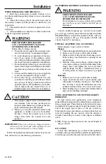
2. When a gas control is installed external to the
appliance, a conduit cover
must
be installed.
See Fig. 1. Place the conduit cover over the
flange, then rotate the conduit cover into
position.
IMPORTANT
:
These gas controls are shipped with pro-
tective seals over inlet and outlet tappings. Do not
remove seals until ready to connect piping.
Follow the appliance manufacturer instructions if avail-
able; otherwise, use the following instructions.
CONVERTING BETWEEN NATURAL AND LP GAS
WARNING
FIRE OR EXPLOSION HAZARD
CAN CAUSE PROPERTY DAMAGE,
SEVERE INJURY, OR DEATH
Do not attempt to use a gas control set for natural
gas on LP gas or a gas control set for LP gas on
natural gas.
Convert standard-opening gas controls from natural
gas to LP gas with the conversion kit included with this
TRADELINE gas control. Part number 393691 will con-
vert from natural to LP gas. Part number 394588 will
convert from LP to natural gas.
INSTALL ADAPTERS TO GAS CONTROL
Install adapters to gas control as follows:
Flanges
1. Choose the appropriate flange for your application.
2. Remove seal over gas control inlet or outlet.
3. Make sure the O-ring fits into the flange groove.
If the O-ring is not attached or is missing, do not
use the flange.
4. With the O-ring facing the gas control, align the
screw holes on the gas control with the holes in the
flange. Insert and tighten the screws provided
with the flange. See Fig. 1. Tighten the screws to
25 inch-pounds of torque to provide a gas-tight
seal.
Bushings
1. Remove seal over gas control inlet or outlet.
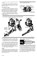
2. Apply moderate amount of good quality pipe
compound to bushing, leaving two end threads
bare. See Fig. 3. On an LP installation, use com-
pound resistant to LP gas.
Do not use Teflon tap
e.
3. Insert bushing in gas control and carefully thread
pipe into the bushing until tight.
USING ADAPTERS TO SOLVE SWING RADIUS
PROBLEMS
In some field service applications, space limitations
make it difficult or impossible to thread the gas control onto
the gas supply pipe. This problem can be resolved for many
installations by using an adapter. Install the adapter on the
end of the supply pipe in place of the gas control by
following the same precautions and instructions that are
used for installing the gas control. After the adapter is
installed, attach the gas control to the adapter as outlined
above.
NOTE: Using an adapter increases the overall length of
the gas control.
LOCATION
Locate the combination gas control in the appliance
vestibule on the gas manifold. In replacement applications,
locate the gas control in the same location as the old control.
!
!
!


