2
TP970 AND TP9600 SERIES PNEUMATIC THERMOSTATS
77-9382—1
INTRODUCTION
This Engineering Data sheet provides detailed information
on the operation of TP970 and TP9600 Series Pneumatic
Thermostats (Thermostats). These Thermostats use the
force-balance design with high nozzle feedback for stability.
The TP970 and TP9600 Series includes the following
thermostat models:
—
TP970A-D and TP9600A, B:
High capacity
Proportional control
Single temperature
—
TP971A-C and TP9610A, B:
Dual temperature
Day/night control (automatic switchover through
diaphragm logic)
Two sensing elements
Individual setpoint control
—
TP972A and TP9620A, B:
High capacity
Heating/cooling control (automatic switchover
through diaphragm logic)
Two sensing elements (one for heating control,
one for cooling control)
—
TP973A, B and TP9630A, B:
Low capacity
Proportional control
Single temperature
—
TP974A:
Room temperature sensor
Used as a remote temperature transmitter for the RP920
Pneumatic Controller
This Engineering Data sheet describes the TP973A, B and
TP9630A, B Thermostats first, because they are the
simplest.
FUNDAMENTALS OF THERMOSTAT
OPERATION
General
In force-balance design, two forces oppose each other until
they are equal, or balanced. The TP970 and TP9600 Series
Thermostats use the force of the bimetal to close the flapper
over the nozzle and the opposing force of the air pressure in
the nozzle chamber to lift the flapper (see the Flapper-
Nozzle Operation section). When the forces are equal, a
force-balance condition exists.
The throttling range setting and the calibration reference
temperature determine the Thermostat span and calibration
point. At control point the nozzle-flapper-bimetal assembly
(acting through the calibration screw, setpoint cam, and the
throttling range (TR) adjustment) has a fixed branchline
pressure (BLP) for each temperature within the temperature
and throttling range settings. The forces within the nozzle-
flapper-bimetal assembly always seek a balanced condition;
giving the same BLP for the same temperature regardless of
fluctuations in main air or the relative positions of the nozzle,
flapper, and bimetal.
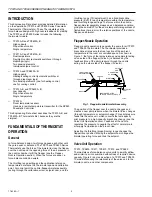
Flapper-Nozzle Operation
Flapper-nozzle operation is generally the same for all TP970
and TP9600 Thermostats. The Thermostat provides a
branchline air pressure that is a function of the ambient
temperature in the room or controlled space. As shown in
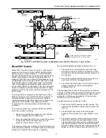
Figure 1, the force of the temperature-sensing bimetal acting
on one side of the flapper (Force A) is balanced by the
feedback force of the pilot pressure through the nozzle
acting on the other side of the flapper (Force B).
Fig. 1. Flapper-Nozzle-Bimetal Assembly.
The position of the flapper over the nozzle changes and
creates a new pilot pressure when the bimetal force changes
(through temperature or setpoint change). This pilot pressure
feeds into the valve unit, which converts the low-capacity
pilot pressure to a high-capacity branchline change (see the
Valve Unit Operation section). Feedback at the nozzle
regulates the pressure to negate the effect of normal main
air supply fluctuations on the branch line.
Adjusting the throttling (proportioning) range changes the
flapper lever position. Moving the setpoint cam changes the
bimetal operating force and thus the setpoint.
Valve Unit Operation
TP970, TP9600, TP971, TP9610, TP972, and TP9620
Thermostats use force-balance valve units to amplify airflow
and minimize air consumption without loss of required device
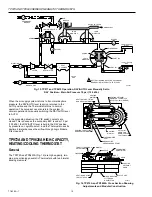
capacity. Figure 2 is a cross-section of a TP970 and TP9600
Thermostat showing the relationship of the valve unit to the
bimetal, nozzle, and other components.
IN BALANCED STATE,
FORCE B EQUALS FORCE A
NOZZLE
FLAPPER
THROTTLING RANGE
ADJUSTMENT
BIMETAL
SETPOINT
CAM
CALIBRATION
SCREW
SETPOINT
KNOB
FORCE B
FORCE A
C6046

