background image

40

31-00400M-01 | Rev10-20

3 - INITIAL CONFIGURATION
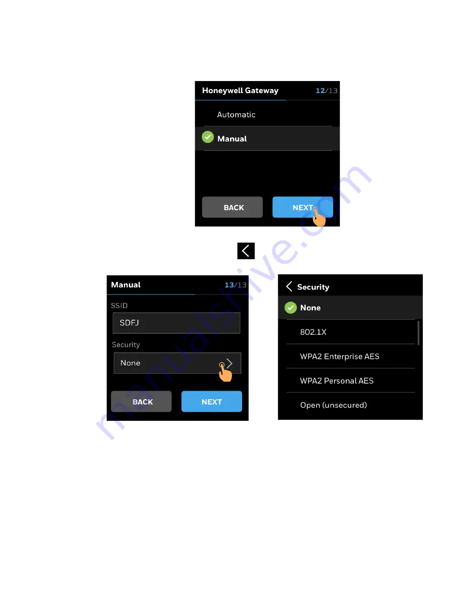
Manual Settings

1. Tap 

Manual 

and tap 

NEXT

Figure 35 

Manual connection

2. User will be prompted to enter 

SSID

 and choose 

Security

.

3. Select the type of security and tap 

.

Figure 36 

Selecting SSID and Security

4. The thermostat automatically start connecting.

Summary of Contents for TC500A

Page 1: ...USER GUIDE U S Registered Trademark Copyright 2020 Honeywell Inc All Rights Reserved 31 00400M 01 Rev10 20 OCTOBER 2020 TC500A Commercial Thermostat ...

Page 2: ......

Page 3: ...Technical Specifications 12 Security requirement 14 Deployments and Maintenance Considerations 15 Getting started 17 TC500A Thermostat at a glance 17 Thermostat Display Overview 17 Presence detection 17 Home Page Main Screen Temperature reading and adjustment 18 Home Page Right Screen Quick access and device management 19 Home Page Left Screen Weather and sensor reading 20 Home screen icon overvie...

Page 4: ...Step 5 Connecting a thermostat 37 Basic Configuration 44 User Management 47 User Roles 47 Configuring the user roles 48 Managing Alarms 57 About Alarms 57 Alarm notification signs 57 Unacknowledged Alarms 58 List of Alarms and their severity 60 Managing Alarms 61 Scheduling 63 About Schedule 63 Setting up a Weekly Schedule 64 Setting up a Holiday Schedule 69 Resetting Schedule 74 Factory reset 76 ...

Page 5: ... customer In no event is Honeywell liable to anyone for any direct special or consequential damages The information and specifications in this document are subject to change without notice Copyright 2020 Honeywell International Inc Waste Electrical and Electronic Equipment WEEE FCC Part 15 compliant This device complies with part 15 of the FCC Rules Operation is subject to the following two condit...

Page 6: ...tion resulting from low shipping storage temperatures to evaporate Investigated according to United States Standard UL 60730 1 and UL60730 2 9 Investigated according to Canadian National Standard s C22 2 No 205 M1983 CNL listed Do not open TC500A Thermostat as it contains no user serviceable parts inside CE declarations according to LVD Directive 2014 35 EU and EMC Directive 2014 30 EU Product sta...

Page 7: ...ate separation of communications wiring and other electrical wiring according to code Keep wiring and controllers at least six feet from large inductive loads power distribution panels lighting ballasts motors etc Failure to follow these guidelines can introduce electrical interference and cause the system to operate erratically Warning By using this Honeywell literature you agree that Honeywell w...

Page 8: ...8 31 00400M 01 Rev10 20 COMMERCIAL TOUCHSCREEN THERMOSTAT ...

Page 9: ...als to connect with sensors or other accessories It also has a built in temperature sensor humidity sensor and proximity sensor Features The device can be easily commissioned through the TC500A Connect Mobile application Easily customizable and intuitive UI Supports BACnet system schedule and holiday configuration Multiple configurable levels of user privilege access for features such as Reminders...

Page 10: ...be interpreted to supersede or modify the local codes and practices of the AHJ Reference documents Commercial Thermostat Datasheet 31 00398M Commercial Thermostat Mounting instructions 31 00399M Commercial Thermostat Quick start guide 31 00401M Abbreviation and Nomenclature Conventions The TC500A Commercial Connected Thermostat uses a 4 inch 480x480 pixel LCD screen for easy navigation and setup U...

Page 11: ... the option selected or the text entered is valid the option to move to the subsequent screen turns blue Tapping the option in blue will toggle to next screen Dimensions Figure 2 Dimensions Swipe right to view or scroll towards left Swipe down to view or scroll towards up Swipe up to view or scroll towards down Tap to select an item Swipe left to view or scroll towards right 3 19 32 91 2 mm 4 15 3...

Page 12: ...lay Display Type 24 BPP TFT display with CTP Resolutions 480x480 pixel Active Display Area 4 diagonally Backlight LCD Dimmable Table 3 Operating Environment Ambient Operating Temperature 32 to 122 F 0 to 50 C Ambient Operating Humidity 10 to 90 relative humidity non condensing Storage Temperature 40 to 150 F 40 to 65 5 C Protection Class IP20 Table 4 Compliances Certificates CE FCC ICES UL cUL RoH...

Page 13: ...ed circuit 100ohms Voltage Output 0 10V 3 of full scale 2K ohms UI x 2 Resistive Input for 10K NTC type II C7021 series for 10K NTC type III C7023 series for 20K NTC TR21 and C7041 series 0 5 C 1 F at 10 32 C 50 90 F 1 1 C 2 F at 1 1 50 C 30 122 F Voltage Input SELV 0 10V 5 of full scale Digital Input Dry contact closure Open circuit 100Kohms Closed circuit 100ohms DO G Y1 Y2 Y3 W1 W 2 W3 Relay Ou...

Page 14: ...ions A firewall is required to isolate the Thermostat Unprotected Internet connections can expose and damage the thermostat system and facility components to cyber attacks from third parties This may cause the thermostat to malfunction and can also be misused for illegal purposes for which the operator may then be held liable Table 7 Electrical Characteristics Rated Impulse Voltage 500 V Construct...

Page 15: ...ommunication bandwidth within the whole system Regular check of the communication failure rate or response rate of the thermostat is helpful to discover and isolate devices being attacked and stop the physical attacks in daily operation Network Communication Notice To keep maximum integration compatibility with third party devices and Fast pack communications are un encrypted as open protocol Impr...

Page 16: ...16 31 00400M 01 Rev10 20 1 ABOUT TC500A THERMOSTAT ...

Page 17: ...0399M TC500A Thermostat at a glance Thermostat Display Overview The images below illustrates the typical screen of TC500A Thermostat screens The 4 inch LCD screen on the thermostat is touch sensitive and shows status of the ther mostat Presence detection TC500A Thermostat has a built in proximity sensor It detects presence of a user up to 1 5 meters and wakes the screen to prepare for user interac...

Page 18: ... Temperature Displays the current indoor temperature 4 Mode Display Orange flame for heat mode blue snowflake for cool mode 5 Wi Fi signal strength 6 Time 7 Adjust temperature Touch the up arrow to increase the desired temperature 8 Desired temperature Displays the desired temperature 9 Adjust temperature Touch the down arrow to decrease the desired temperature 10 Temperature Slider Use finger to ...

Page 19: ...Description 1 Brightness Tap to increase or decrease the brightness of display 2 Alerts Tap to view active alarms and reminders 3 Schedule Tap to set the schedules 4 Temperature Units Tap to toggle between Fahrenheit or Celsius 5 Override Tap to override unoccupied or standby modes to allow setpoint adjustments 6 Contractor information Tap to view contractor information 7 Config Tap to configure t...

Page 20: ...20 31 00400M 01 Rev10 20 2 GETTING STARTED Home Page Left Screen Weather and sensor reading Note Home page Left Screen varies according to the sensor connected to the thermostat 4 4 3 1 2 ...

Page 21: ...e screen icon overview Table 10 Home screen icon overview Icon Description High severity alert Medium severity alert Low severity alert Auto mode Emergency heat mode Heating mode Cooling mode Occupied mode Standby mode Unoccupied mode Wi Fi signal strength ...

Page 22: ...Screen ON LED Lighting OFF Heating The orange light pulses when in heating and auto mode Screen OFF LED Lighting ON Light stops pulsing when indoor temperature reaches the set point Cooling The blue light pulsing when in cooling and auto mode Screen OFF LED Lighting ON Lighting stops pulsing when indoor temperature reaches the set point Off Screen OFF LED lighting OFF ...

Page 23: ...e details Setting an administrator password Setting up a network connection and choosing the network connection type WARNINGS To reduce the risk of electrical shock do not open the thermostat There are no user serviceable parts inside Refer servicing to a qualified service personnel only Cleaning Use a dry cloth to clean the product Do not use liquid cleaners or aerosol cleaners Water and moisture...

Page 24: ...t power up Honeywell logo followed by welcome screen appears on the display 1 Tap anywhere on the screen Welcome screen appears Figure 3 Welcome screens 2 Tap LET s BEGIN screen to start the configuration Figure 4 Welcome screen 3 User will be prompted to select default language Tap on the desired language ...

Page 25: ... Language 4 Tap Next Platform Configuration screen appears Step 2 Choosing a configuration platform The TC500A can be configured via mobile application or through the thermostat screen The user can select one of the options to initiate the configuration Figure 6 Platform Configuration ...

Page 26: ...een Figure 7 Platform configuration app 3 Scan the QR code by aligning QR code on Honeywell app within the frame 4 The thermostat will be connected to the application Step 3 Configuration through thermostat touchscreen display To configure the thermostat via on screen display 1 On the platform configuration screen tap Thermostat 2 Tap NEXT Device Name screen appears Figure 8 Platform configuration...

Page 27: ...lled It assist user to easily identify the device during remote operation of the thermostat To name a thermostat 1 Tap on the text field A keyboard will be displayed on screen to enter the device name Figure 9 Device name 2 Enter the device name Naming Rules Device name should not be more than 20 character 3 After entering a valid device name tap NEXT The device name will be saved Figure 10 Saving...

Page 28: ...it F or C 2 Tap Next Figure 11 Selecting Temperature Unit After selecting the temperature unit user will be prompted to select the type of equipment The TC500A is designed to control Heat Pump or Conventional HVAC heating and cooling applications It can control up to three stages of heating and three stages of cooling in conventional systems and up to two compressors and two stages of auxiliary he...

Page 29: ... 1 Tap Conventional Figure 12 Select Conventional type of equipment 2 Select the number of Cooling stages Tap corresponding number to select number of stages Figure 13 Select number of colling stages 3 Tap NEXT User will be prompted to select the Heating Type Stages 4 Tap corresponding number to select number of stages To set up modulating heating type tap on Modulating toggle ...

Page 30: ...ONFIGURATION Figure 14 Select heating stage 5 Use the toggle to enable the heat stages 6 Swipe the slider to select the desired percentage of output Figure 15 Select modulated heating 7 Tap None and tap NEXT in case no heating is required ...

Page 31: ... Rev10 20 31 STEP 3 CONFIGURATION THROUGH THERMOSTAT TOUCHSCREEN DISPLAY Figure 16 No heatingt 8 Using set the desired Setpoints for Occupied Standby and Unoccupied modes Figure 17 define the setpoints 9 Click NEXT ...

Page 32: ...g up Heat Pump 1 Tap Heat Pump Figure 18 Select Heat pumpt 2 Select the type of Heat Pump and Reversing Valve Figure 19 Select Type of Heat Pump and Reversing Valve 3 Select the number of Compressor stages Tap corresponding number to select number of stages ...

Page 33: ... 4 Tap NEXT User will be prompted to select the Aux Heating Type Stages 5 Tap corresponding number to select number of stages To set up modulating heating tap on Modulating toggle Figure 21 Select modulating Aux heating type 6 Use the toggle to enable the stage 1 heat 7 Swipe the slider to select the desired percentage of output ...

Page 34: ...1 Rev10 20 3 INITIAL CONFIGURATION Figure 22 Enable stage 1 heat 8 Tap None and tap NEXT in case no heating is required Figure 23 No heating 9 Using set the desired Setpoints for Occupied Standby and Unoccupied modes ...

Page 35: ...electing the equipment type to prevent unauthorized changes user will be prompted to enter installer pin Password rules Password should be alphanumeric It should be between 4 to 12 characters To set up a installer pin 1 Tap on the text field A keyboard will be displayed on screen to enter the device name Figure 25 Setting Installer Pin ...

Page 36: ...TIAL CONFIGURATION 2 Enter the Installer Pin and tap Figure 26 Entering Installer Pin 3 Enter a valid Installer PIN and tap NEXT Figure 27 Valid Password 4 Fill the Contractor Information Figure 28 Contractor Information 5 Tap NEXT ...

Page 37: ... network allows you to connect to the cloud server and control your thermostat from a smartphone during initial setup user will be prompted to select how to set the thermostat to connect to the Internet The TC500A Thermostat can be connected to the Internet using Local router Honeywell Gateway or BACnet IP In order to connect to Wi Fi 1 Select Wi Fi Figure 29 Select Wi Fi 2 Tap NEXT 3 User will be...

Page 38: ...eywell Gateway In order to connect through Honeywell Gateway 1 Tap Honeywell Gateway Figure 30 2 User will be prompted to choose between Automatic or Manual connection Automatic Settings 1 Tap Automatic Figure 31 Automatic connection 2 The thermostat automatically start connecting ...

Page 39: ... THERMOSTAT Figure 32 Connection in progress 3 If the connection is successful Click DONE Figure 33 Successful connection 4 If the connection is unsuccessful user can RETRY or SKIP setting Wi Fi connection Figure 34 Unsuccessful Wi Fi connection ...

Page 40: ...Manual Settings 1 Tap Manual and tap NEXT Figure 35 Manual connection 2 User will be prompted to enter SSID and choose Security 3 Select the type of security and tap Figure 36 Selecting SSID and Security 4 The thermostat automatically start connecting ...

Page 41: ... STEP 5 CONNECTING A THERMOSTAT Figure 37 Connection in progress 5 If the connection is successful Click DONE Figure 38 Successful connection 6 If the connection is unsuccessful user can RETRY or SKIP setting Wi Fi connection ...

Page 42: ...is BACnet IP connected using a wireless connection to a Wi Fi router access point In order to connect through BACnet IP over Wi Fi 1 Tap BACnet IP Figure 39 Select BACnet IP 2 User will be prompted to select from available networks Figure 40 Choose a network 3 Select the network enter password and tap ...

Page 43: ...re 41 Enter Password 4 The thermostat automatically start connecting Figure 42 Connection in progress 5 If the connection is successful Click DONE Figure 43 Successful connection 6 If the connection is unsuccessful user can RETRY or SKIP setting Wi Fi connection ...

Page 44: ...ermostat 1 On the Home page tap the Config icon The Config main page appears with all types of configuration options available in the thermostat Figure 44 Select Configuration 2 Tap Basic Basic Configuration page appears Figure 45 Basic Configuration 3 Tap General or Equipment to modify the configuration 4 Tap the option to modify from the list For step by step setup refer guided initial setup ...

Page 45: ...sic configuration General User can modify following configuration using General tab in Basic configuration Swipe up or down to view additional options on the screen For step by step setup refer the initial setup Figure 46 Basic Configuration General ...

Page 46: ... 3 INITIAL CONFIGURATION Basic configuration Equipment User can modify following configuration using Equipment tab in Basic configura tion For step by step setup refer the initial setup Figure 47 Basic Configuration Equipment ...

Page 47: ... for user requiring limited control of thermostat such as store clerks receptionist 3 Advanced User Group Owner has access to read and write all components related to advance control The advanced user will be able to perform system overrides schedule changes or modify the basic configuration This type of user role is applicable for user requiring more control of thermostat such as store manager bu...

Page 48: ...pe of users and permission follow the steps below 1 On the home screen swipe right to view Quick access and device management home screen Figure 48 Navigate to Quick access and device management 2 Tap Config Config management page will appear Figure 49 Quick access and device management ...

Page 49: ...ev10 20 49 CONFIGURING THE USER ROLES 3 Tap User Management Figure 50 Configuration Page Visitor To manage the Visitor user role 1 Select Visitor Tap to select View Type and Permission Figure 51 User Management page ...

Page 50: ...on to allow visitor to override the Setpoints Note Visitor will have access to increase or decrease temperature in Simplified view only Figure 53 Set Visitor Permission 4 Tap to go to previous menu 5 If passcode is not entered a notification banner appears Tap Yes to enter the passcode Figure 54 No passcode ...

Page 51: ...s if permitted to change the setpoints in occupied or unoccupied mode User can tap or to increase or decrease the temperature In non occupied state the simple view has a override toggle option on top User must slide the toggle to override to make changes in setpoint Figure 55 Simple View Occupied Figure 56 Simple view Unoccupied ...

Page 52: ...es a visual indication of heating or cooling in different colors The same is also represented using horizontal bars in the display Table 13 Increasing Temperature Table 14 Decreasing Temperature Basic User To manage the Basic User role 1 Select Basic User and Tap Figure 57 User Management screen Low Medium High Low Medium High ...

Page 53: ... ROLES 2 Set a Passcode View Type and user Permission Password should be alphanumeric It should be between 4 to 12 characters Figure 58 Basic user Figure 59 Basic User Permission 3 Select the View Type Scroll up or down to view additional options ...

Page 54: ...lect View type 4 Tap to go to previous menu 5 If passcode is not entered a notification banner appears Tap Yes to enter the passcode Figure 61 No passcode Advanced User To manage the Advanced User role 1 Select Advanced User and Tap Figure 62 Advanced User ...

Page 55: ...t a Passcode Permission Password should be alphanumeric It should be between 4 to 12 characters Figure 63 Advance user 3 Tap to go to previous menu 4 If passcode is not entered a notification banner appears Tap Yes to enter the passcode Figure 64 No passcode ...

Page 56: ...ANAGEMENT Installer To manage the Advanced User role 1 Select Installer and Tap Figure 65 User Management 2 Set or change a Passcode Permission Password should be alphanumeric It should be between 4 to 12 characters Figure 66 Installer ...

Page 57: ...s into High Medium and Low categories You can view and acknowledge the alarms on the TC500A screen Additionally the alarm icon on the Home page shows active alarms as an icon notification such as Alarm notification signs The alarm menu notification icon has different color codes to indicate the severity of the alarm The following table describes the available signs with color codes of the alarm pa...

Page 58: ...nagement home screen tap the ALERT icon Alert page displays Figure 67 Home page Alert Tab 2 The alert page appears Select Alarms List of unacknowledged alarms displays Figure 68 Alert Preference Alarm Note Under the ALARM tab tap the Red orange or yellow colored Alarms The relevant data points list appears to acknowledge the alarms Red icon Displays only the data points with High severity alarm Or...

Page 59: ... Tap ACKNOWLEDE to view additional information and acknowledge the alarm Figure 70 Acknowledge alarms Note Except Alarms Unknown Time and Wi Fi Network Not Configured all alarms can be acknowledged by tapping ACKNOWLEDGE Note For Unknown Time set Date and Time page appears Click SAVE to acknowledge alarms Note For Wi Fi Network Not Configured Configuration Settings appear Select the Wi Fi network ...

Page 60: ...ater Flow Alarm High Internal temperature Sensor Failure High Sylk Device Communication Failure High Analog Input Fault High Discharge Air Temperature Out of Range High Space Temperature Out of Range Protection High Internal Temperature Sensor Failure Medium Internal Humidity Sensor Failure Medium Internal Proximity Sensor Failure Medium Unknown Time Medium Network Communication Failure Alarm Low ...

Page 61: ...e sensor going below the frost setpoint High Proof of water flow Alarm Heat pump proof of water is for water source heat pumps only and needs extra configuration water flow detector If the stage should be on then the input indicates loss of water flow in a Heat pump application Interlock stage The controller shall disable the heat pump compressor High Wi Fi Network Not Configured If user selects W...

Page 62: ...pplication shall disable all control functions associated with the failed sensor i e it will react as if the sensor was not configured 2 OAT out of range Will not disable control function check equipment for proper operation High failure Medium out of range Mixed air sensor failure alarm 1 Open short limit is detected on mixed air sensor UI1 UI2 UIO1 UIO2 2 MAT outside of range MA sensor 40F or MA...

Page 63: ... schedule overrides the holiday and standard schedules within a schedule set How schedules works When you set up schedules it is important to understand the relationship of the schedules in the schedule set and how to use each one Standard schedule Use weekly schedules to control equipment with ON and OFF commands during routine hours of operation This schedule may contain ON commands for operatin...

Page 64: ...he schedule main page appears which lists all types of schedules available in the thermostat Figure 71 Select Schedule 2 Tap Weekly to add a new schedule The corresponding regular schedule page appears Figure 72 List of types Schedules 3 Select a day where you want to add a new schedule The corresponding day page appears which contains existing schedules ...

Page 65: ...ay 4 To add a new schedule tap on the Unoccupied button The Create Event page will appear Figure 74 Adding a schedule 5 Select Start and End time of schedule by tapping clock symbol Select the mode Occupied or Standby from the selections below it Figure 75 Add Time and select type of schedule ...

Page 66: ...66 31 00400M 01 Rev10 20 6 SCHEDULING 6 Tap Save The corresponding day page with all schedules will appear Figure 76 Save Schedule 7 Tap to exit scheduling ...

Page 67: ...from the Weekly schedule page To change or delete an existing weekly schedule 1 On the Weekly schedule page tap the schedule to be modified The Edit Event page will appear Figure 77 Editing a Regular Schedule 2 Select the new Start and End time and mode Tap Save to save changes or Tap DELETE to delete the schedule Figure 78 Edit Event ...

Page 68: ...schedule from one day to another 1 Navigate to Weekly schedule page from where schedule is to be copied Select day to copy Tap to copy schedules Copy screen will appear Figure 79 Copy Schedule 2 Tap on the days of the week for which scheduled is to be copied Figure 80 Select Days 3 Tap Confirm A banner indicating successful copying will pop up ...

Page 69: ...a Holiday Schedule To schedule a holiday 1 On the Home page tap the Schedule icon The schedule main page appears which lists all types of schedules available in the thermostat Figure 82 Select Schedule 2 Tap Holiday to add a new holiday schedule The corresponding Holiday schedule page appears ...

Page 70: ...70 31 00400M 01 Rev10 20 6 SCHEDULING Figure 83 List of types Schedules 3 Tap to add a Holiday Note User can create unlimited number of Holidays Figure 84 Adding new Holiday 4 Tap on Set Date ...

Page 71: ...TTING UP A HOLIDAY SCHEDULE Figure 85 Creating Holiday 5 Tap on Floating date or Specific Date Set Date page displays Figure 86 Set Date 6 Tap to select a date User will be able to choose number of days for specific date holiday ...

Page 72: ... 01 Rev10 20 6 SCHEDULING Figure 87 Set Start date 7 Tap Save Deleting a Holiday Schedule To delete a holiday 1 On the Holiday page swipe right to delete Holiday Trash bin appears on right Figure 88 Select Holiday ...

Page 73: ...0 20 73 SETTING UP A HOLIDAY SCHEDULE 2 Tap to delete the Holiday Figure 89 Delete Holiday 3 User will be prompted to confirm to delete holiday Tap DELETE Figure 90 Pop up to delete Holiday 4 The holiday will be deleted ...

Page 74: ...ap the Config icon The Config main page appears which lists all types of configuration options available in the thermostat Figure 91 Select Configuration 2 Tap Reset to Default to reset the schedules Config page appears User will be prompted to reset the schedule or the device Figure 92 Reset to default ...

Page 75: ...1 Rev10 20 75 RESETTING SCHEDULE 3 Tap Reset Schedule User will be prompted to confirm the action before reset Figure 93 Reset Schedule 4 Tap YES to reset schedule Progress screen appears Figure 94 Reset Schedule ...

Page 76: ...eset weekly schedule and setpoints of occupied unoccupied and standby to factory default Figure 95 Reset Confirmation Factory reset To restore factory default setting 1 On the Home page tap the Config icon The Config main page appears which lists all types of configuration options available in the thermostat Figure 96 Select Configuration ...

Page 77: ...set the thermostat Config page appears User will be prompted to reset the schedule or the device Figure 97 Reset to default 3 Tap Reset All User will be prompted to confirm the action before reset Figure 98 Reset All 4 Tap YES to reset schedule Progress screen appears ...

Page 78: ...78 31 00400M 01 Rev10 20 6 SCHEDULING Figure 99 Reset Schedule 5 Upon successful reset user will be notified by a notification banner Figure 100 Reset All ...

Page 79: ...ll Building Technologies Honeywell 715 Peachtree Street NE Atlanta GA 30308 customer honeywell com buildingcontrols honeywell com U S Registered Trademark 2019 Honeywell International Inc 31 00400M 01 Rev10 20 ...

Reviews: