TC500A-N/TC500A-W COMMERCIAL THERMOSTAT
31-00399M-01 | Rev.10-20
4
Mounting wallplate on the dry wall
The thermostat wallplate can be mounted vertically on the
wall. It supports 18-22 AWG (0.5-0.75mm2) wires.
1.
Before mounting the wallplate, make sure that the
wire ends (not cables) are stripped for the length
marked on the wallplate.
Fig. 4. Wire strip length
2.
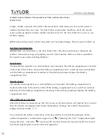
Position and level the wallplate along the wall and
mark the drilling location using a pencil.
Fig. 5. Wallplate drilling locations
3.
Remove the wallplate and drill two pilot holes on the
wall, on the marks. For drywall, drill 3/16-in. holes.
For firmer material such as plaster, drill 7/32-in.
holes.
4.
Gently tap anchors (provided in kit) into the pilot
holes until flush with the wall.
5.
Pull the wires through the wiring opening of the wall
-
plate and position the wallplate over the mounting
holes.
6.
Insert the screws into the holes and tighten (screw
torque 0.1Nm).
Mounting the wallplate on the gang
box (optional)
The thermostat wallplate can be mounted vertically on a
US 2”*4” or UK 75*75mm gang box which is already
installed onto the wall and wired.
1.
Before mounting the wallplate, make sure that the
wire ends (not cables) are stripped for the length
marked on the wallplate.
2.
Pull the wires through the wiring opening of the wall
-
plate, and position the wallplate along the gang box
to align the mounting holes. For gang box screw
holes, refer to Fig. 5.
3.
Insert the screws into the holes and tighten.
4 x 11/32”
(9mm)
2 - 3/8”
(60.3mm)
(UK 75X75cm
gang box
screw holes)
4 x 3/16”
(4.5mm)
Drilling location for
wall mounting
Drilling location for wall mounting
3 - 1/4”
(82.75mm)
(US 2”X4” gang box
screw holes)