


T775 SERIES 2000 ELECTRONIC STAND-ALONE CONTROLLERS
63-7147—3
24
3 Stage Reciprocating Chiller – T775L
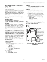
Application Description
The T775L is controlling the return water in a reciprocating
chiller with fast-dump freeze protection, low temperature
cutoff, and optional low pressure cutoff.
Sensor Designation
This device application requires two sensors.
• Sensor A is sensing return water and controlling three
stages of cooling.
• Sensor B is sensing discharge water and is controlling
relay 4 for freeze protection.
Operation
Return water is one indication of the cooling load in the water
loop. For example, the higher the return water temperature
the higher the apparent load and more stages of refrigeration
or cooling would be required. If a large load is quickly dropped
from the loop, or for some reason water flow through the
chiller is reduced, discharge water temperature may drop
rapidly to freezing conditions. In this example, Sensor B in the
discharge water will prevent damage to the system by
fast-
dumping
all cooling stages upon close-to-freezing conditions.
Programming Example
Program in Setup:
Press and hold the
MENU
button for 5 seconds to enter
Setup mode. Select the Outputs menu, and then select:
— # Relays = 3
— # Loops = 1
— Options
→
DI Options = Disable
(acts as low pressure cutoff)
— Loop 1
→
# Relays = 3
— Loop 1
→
Reset = NO
Loop 1: Chiller cooling
Program for:
— Setpoint = 62° F (17° C)
— Throttling Range = 12° F (-11° C)
— Sensor A
— Cool
Relay 4: Low temperature cutoff for freeze protection
Program for:
— Setpoint = 40° F (4° C)
— Differential = 4° F (-16° C)
— Sensor B
— Heat
IMPORTANT
After the desired value is selected, be sure to press
the
#
or
$
or
HOME
button in order to save that
value in the controller’s memory.
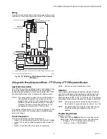
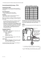
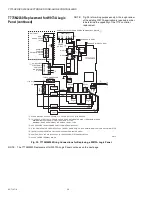
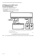
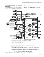
Wiring
All output relays should have a common power wiring source,
which may or may not be the same as the T775 power wiring.
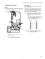
Fig. 29. T775L Wiring - Reciprocating Chiller.
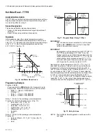
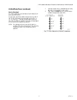
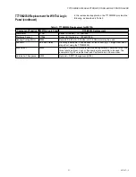
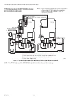
Fig. 30. Chiller Control Staging Behavior (when the
effective setpoint = 62° F (17° C)).
SENSOR A
(RETURN WATER)
SENSOR B
(DISCHARGE
WATER)
DIGITAL INPUT
(LOW PRESSURE
CUTOFF)
L1 (HOT)
L2
T
T
T
T
2
1
C
NC
C
NO
NO
C
NC
NO
C
NC
NC
120
120 VAC
COM
COM
240
C
NO
COOL #1
COOL #2
COOL #3
1
2
POWER WITH 24 VAC OR 120/240 VAC AT THE APPROPRIATE TERMINAL BLOCK.
24 VAC POWER TERMINAL BLOCK.
M25514
RELAY
4
RELAY
3
RELAY
1
RELAY
2
T775L
M13895
STAGE 2 ON
STAGE 3 ON
STAGE 1 ON
-33%
STAGES
HYST.
0%
33%
67%
STAGE 1
STAGE 2
STAGE 3
1
1
CHILLER DISCHARGE WATER TEMPERATURE
58°F
62°F
66°F
70°F
STAGE ENERGIZES
STAGE DE-ENERGIZES
THROTTLING RANGE (12°F)


