


T775 SERIES 2000 ELECTRONIC STAND-ALONE CONTROLLERS
21
63-7147—3
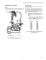
Wiring
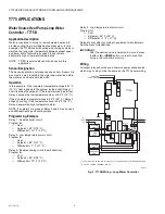
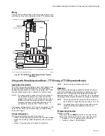
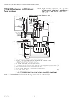
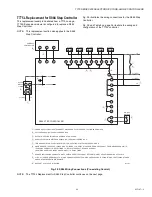
All output relays should have a common power wiring source,
which may or may not be the same as the T775 power wiring.
Fig. 24. T775P Wiring - Multi-Stage Chiller Control
(No Reset).
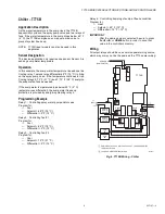
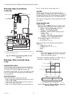
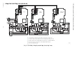
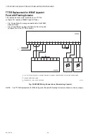
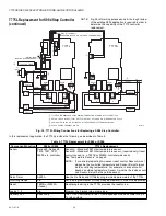
4 Stage with Pump Output and Reset – T775P using a T775S Expansion Module
Application Description
The T775P is providing multistage boiler control based on the
boiler's discharge water temperature. Four stages and a
dedicated pump output are used in this example. The T775P
uses the eighth output relay to energize the primary pump.
NOTE: The pump output is always the last relay output. In
this application example, four relays are used for
staged boiler control. A T775S expansion module is
added to provide the additional relay for the pump.
However, the pump must be the last relay, so it is
configured as relay 8 on the T775S module.
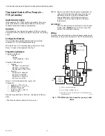
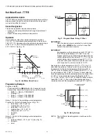
Any number of stages from 1 to 12 can be configured (T775P
and T775L models). The throttling range is divided equally
among the stages.
Sensor Designation
This device application requires three sensors.
• Sensor A is sensing discharge water and controls 4 stages.
• Sensor B is sensing outside temperature and is used for
reset.
• Sensor C is sensing the return water temperature.
NOTE: Control can be to either sensor A or C.
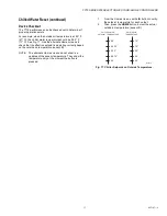
Operation
As the heating load increases additional stages of heat will
cycle ON as the boiler water temperature decreases. In this
example, the T775P provides four stage control when the
effective setpoint is 200° F (93° C). (See Fig. 25.) The primary
circulating pump energizes whenever any stage is energized.
NOTE: The pump output must always be the last relay on
the controller or expansion module (relay 4, 8, or 12).
NOTE: For applications with 3 stages or less with a pump
output, an additional expansion module is not
needed.
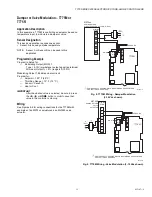
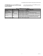
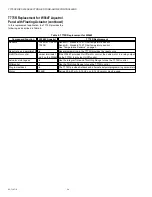
Programming Example
Program in Setup:
Press and hold the
MENU
button for 5 seconds to enter
Setup mode. Select the Outputs menu, and then select:
— # Stages = 4 (T775 assigns pump to Relay 8)
— Options
→
Reset = YES-BOILER
T
T
M28008
T
T
SENSOR A
(CHILLER DISCHARGE WATER)
C
NO
NC
C
NO
NC
C
NC
NO
C
NC
NO
T
T
RELAY
1
C
+
RELAY
4
RELAY
3
RELAY
2
T775P
SENSOR C
(CHILLER
RETURN WATER)
SENSOR B (OUTSIDE AIR)
120
COM
240
1
2
120 VAC
L1
(HOT)
L2
CHILLER 1
L1
(HOT)
L2
CHILLER 2
CHILLER 3
PUMP
POWER WITH 24 VAC OR 120/240 VAC AT THE APPROPRIATE TERMINAL BLOCK.
24 VAC POWER TERMINAL BLOCK.
1
2


