Honeywell SUPER TRADELINE S8610U Installation Instructions Manual Download Page 15

S8610U UNIVERSAL INTERMITTENT PILOT GAS IGNITION CONTROL

15

69-1955

SETTINGS AND ADJUSTMENTS

DIP Switch (S1) Settings

When replacing an existing ignition control with the 
S8610U, refer to Table 2 on page 2 for the correct DIP 
switch settings.

NOTE: Refer to Table 11 for lockout control of DIP 

switch timing settings.

IMPORTANT

Do not power the ignition control prior to setting 
the DIP switches.

The following timing parameters may be set with this 
2-position DIP switch. 

Prepurge

To select Prepurge, set 

SW1

 according to Table 10

Trial for Ignition (TFI)

To select the Trial for Ignition timing, set 

SW2

 according to 

Table 10.

NOTE: The default factory settings (all OFF) are in 

Bold


in Table 10.

Fig. 6. DIP Switch (S1) and Jumper (P4) Location.

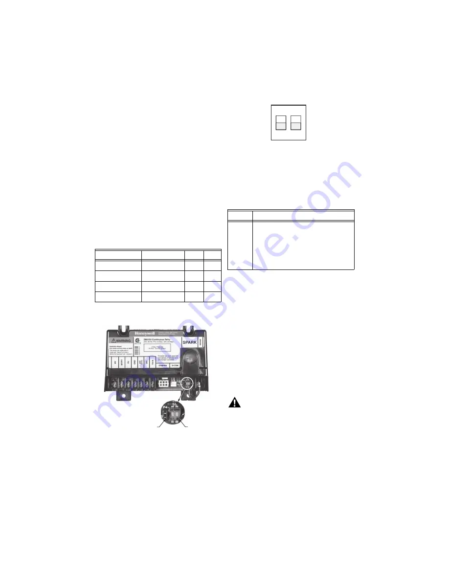
Fig. 7. DIP Switch (S1) - shown with factory default 

settings (OFF) for SW1 and SW2.

Jumper

This jumper (labeled P4) is used to lock the operating 
sequence selected by the DIP switch settings. See Fig. 6 
for jumper location.

IMPORTANT

Once the Jumper has been pulled or the module 
starts the 10

th

 “Call for Heat”, the control operat-

ing sequence is permanently locked and cannot 
be reset by replacing the jumper or by resetting 
the Dip Switch.

CHECKOUT

Check out the gas control system:

• At initial installation of the appliance.
• As part of regular maintenance procedures. 

Maintenance intervals are determined by the 
application. 
For additional information, See “Planning the 
Installation” on page 4.

• As the first step in troubleshooting.
• Any time work is done on the system.

WARNING

Fire or Explosion Hazard.
Failure to heed these warnings may cause fire 
or explosion with property damage, injury, or 
loss of life.

1. If you smell gas or suspect a gas leak, turn off 

gas at manual service valve and evacuate the 
building. Do not try to light any appliance, do 
not touch any electrical switch or telephone in 
the building until you are sure no spilled gas 
remains.

2. Gas leak test must be done as described in th

steps below on initial installation and any time 
work is done involving the gas piping.

Table 10. DIP Switch (S1) Settings.

Prepurge

Trial For Ignition

SW1

SW2

None

90 seconds

OFF

OFF

30 seconds

90 seconds

ON

OFF

None

15 seconds

OFF

ON

30 seconds

15 seconds

ON

ON

M23618

S1 DIP SWITCH

P4 JUMPER

Table 11. Jumper Usage.

Jumper

Action to lock the control’s operating sequence

P4

To ensure proper system operation (after 
installation and checkout), pull jumper to 
lock the DIP switch settings.

NOTE: If jumper is not removed during 

installation, the ignition control 
locks the DIP switch settings after 
the 10

th

 “Call for Heat” cycle.

ON

1

2

S1

M23587

Summary of Contents for SUPER TRADELINE S8610U

Page 1: ... adapt the existing spark cable Rajah stud nail or other to the spark terminal on the control module It also help assure proper marking of the wires attached to the existing control and a label with LED code information that can be affixed in the appliance IMPORTANT The S8610U control module is not designed to replace controls with Flame sensing other than by flame rectification White Rodgers Cycl...

Page 2: ...610C1013 S8610C3001 S8610F1008 S8610F1016 S8610F1024 S8610F1032 OFF OFF S8610H1004 OFF ON S8610H1012 OFF OFF S8610H1020 OFF ON S8610H1038 S8610H1046 S8610H1053 OFF OFF S8610H1061 OFF ON S8610H1079 S8610H1095 S8610H3000 OFF OFF S8610H3018 OFF ON S8610H3026 S8610M1003 OFF OFF S8610M1011 OFF ON S8610M1029 S8610M3009 OFF OFF S8610M3017 OFF ON S8610U1003 S8610U1011 OFF OFF S8620C1003 S8620C1011 OFF ON ...

Page 3: ...BKG 1 G65BKG 2 G65BKG 3 G65BKM 1 G65BKM 2 G65BKM 3 G65BLG 1 G65BLG 2 G65DBG G65DBM 1 G65DBM 2 G65DBM 3 G65DCM 1 G65DFG G65DFM 1 G65DKG G65DKM G65DKM 1 G65DLM 1 G65FBG G65FFG G65FKG OFF OFF Table 2 S8610U Replaces These Modules Continued Vendor Model SW1 SW2 G66AG 1 G66AG 2 G66BG 1 G66MG 1 G66MG 2 G66NG 1 OFF OFF G67AG 3 G67AG 4 G67AG 7 G67AG 8 G67AG 9 G67AG 10 G67AG 11 G67BG 2 G67BG 3 G67BG 4 G67B...

Page 4: ...for the ignition control module Corrosive Chemicals Corrosive chemicals can attack the ignition control module and gas control eventually causing a failure If chemicals are used for routine cleaning make sure they do not reach the controls Where chemicals are suspended in air as in some industrial or agricultural applications use a NEMA 4 enclosure for the ignition control module Dust or Grease Ac...

Page 5: ...rm Pre Installation Safety Check The pre installation checks described below must be done before the replacement ignition control module is installed If a condition that could result in unsafe operation is detected the appliance should be shut off and the owner advised of the unsafe condition Correct any potentially unsafe condition before proceeding with the installation The following safety chec...

Page 6: ...ield wiring terminals Operating ambient temperatures between 40 F 40 C and 165 F 74 C Relative humidity below 95 non condensing Protection from water steam or corrosive chemicals that are used to clean the appliance Protection from dripping water such as from an overfilled humidifier or from condensation Protection from dust or grease accumulation IMPORTANT Do not mount with terminals facing up Fi...

Page 7: ...sor stud on the pilot burner igniter sensor Connect Ignition Control Module CAUTION Equipment Damage Hazard Check the wiring diagram provided on the appliance and compare with Table 5 through Table 8 beginning on page 8 Carefully follow any special instructions affecting the general wiring procedures outlined in this section 1 Connect the wires to the module as shown in the wiring tables Table 5 t...

Page 8: ...t a vent damper was not installed or if it did not have a vent damper connector then connect the 25V 2 or 24V wire from the old module to the TH W terminal on the S8610U Do not use the 24V terminal on the S8610U If the old module had a vent damper connect it to the P1 connector on the module and wire the terminals as indicated in the table 25V 2 or 24V used only in systems where plug in cable conn...

Page 9: ...79 Y79A module b b Discard wires between Y79A and module as follows Red to 3 Black to 2 White to GR Discard wire between transformer and 6 Y79A module c c Discard wires between Y79B and module as follows White to 3 Black to 1 Brown to GR Discard wire between transformer and 6 Main Valve Operator MV 3 3 Y79B MV MV 3 Main Valve and Pilot Common MV PV GR GR GR GROUND 5 Pilot Valve Operator PV 1 1 Y79...

Page 10: ...om E1 which is tagged Thermostat Flame Sensor SENSE d d Important If the USI 715U with combination igniter sensor is not used remove black jumper quick connect from Remote Sense terminal of S8610U Cut jumper wire at circuit board and discard e e Labeled OPT SENSOR on USI 715U No external connection if combination igniter sensor is used d d Igniter Sensor SPARK IGN IGN IGN Table 8 Conversion from C...

Page 11: ...ves as the common grounding area If there is not good metal to metal contact between the pilot burner and ground run a lead from the pilot burner to ground NOTE Earth ground is not required Wiring Connections Use Fig 2 and Table 9 to make the remaining wiring connections Fig 3 Fig 5 beginning on page 12 illustrate typical wiring connections in heating systems with atmospheric burners and with powe...

Page 12: ... LEG TO TRANSFORMER ONCE POWERED UP WITH VENT DAMPER CONNECTED MODULE WILL OPERATE ONLY WITH DAMPER CONNECTED FOR SINGLE ROD APPLICATIONS CONNECT JUMPER WIRE TO THE REMOTE SENSE CONNECTOR FOR TWO ROD APPLICATIONS REMOVE JUMPER WIRE BY CUTTING IT AS CLOSE AS POSSIBLE TO THE BASE OF THE MODULE DISCARD CLIPPED WIRE AND FIRMLY ATTACH THE SENSOR WIRE FROM THE IGNITER SENSOR ASSEMBLY TO THE REMOTE SENSE...

Page 13: ...R WIRE TO THE REMOTE SENSE CONNECTOR FOR TWO ROD APPLICATIONS REMOVE JUMPER WIRE BY CUTTING IT AS CLOSE AS POSSIBLE TO THE BASE OF THE MODULE DISCARD CLIPPED WIRE AND FIRMLY ATTACH THE SENSOR WIRE FROM THE IGNITER SENSOR ASSEMBLY TO THE REMOTE SENSE CONNECTOR M23617 1 2 3 4 5 6 THERMOSTAT L1 HOT L2 LIMIT CONTROLLER 2ND OPERATOR 1ST OPERATOR PILOT COM MAIN VALVE DUAL VALVE COMBINATION GAS CONTROL P...

Page 14: ...ROD APPLICATIONS REMOVE JUMPER WIRE BY CUTTING IT AS CLOSE AS POSSIBLE TO THE BASE OF THE MODULE DISCARD CLIPPED WIRE AND FIRMLY ATTACH THE SENSOR WIRE FROM THE IGNITER SENSOR ASSEMBLY TO THE REMOTE SENSE CONNECTOR 1 2 3 4 5 6 REMOTE SENSE JUMPER WIRE CLIPPED CLOSE TO BOARD TWO ROD SENSOR WIRE FROM IGNITER SENSOR 6 THERMOSTAT L1 HOT L2 1 LIMIT CONTROLLER 2 4 3 M23586 AIR PROVING SWITCH COMBUSTION ...

Page 15: ...out the gas control system At initial installation of the appliance As part of regular maintenance procedures Maintenance intervals are determined by the application For additional information See Planning the Installation on page 4 As the first step in troubleshooting Any time work is done on the system WARNING Fire or Explosion Hazard Failure to heed these warnings may cause fire or explosion wi...

Page 16: ...r main burner 6 Set thermostat below room temperature and wait one minute before continuing Step 6 Check Normal Operation 1 Turn on the gas supply 2 Set thermostat or controller above room tempera ture to Call for Heat 3 Make sure pilot lights smoothly when gas reaches the pilot burner 4 Make sure main burner lights smoothly without flashback 5 Make sure burner operates smoothly without float ing ...

Page 17: ...rating Sequence OPERATING SEQUENCE CALL FOR HEAT RECEIVED FROM THERMOSTAT POWER TO MODULE AND SELF CHECK IDLE NOT POWERED RUN YES TRIAL FOR IGNITION TIMER STARTED SPARK ON OPEN PILOT GAS VALVE FLAME PROVED FLAME STABILIZATION 2 SECONDS YES NO RETRY OPEN MAIN GAS VALVE CLOSE MAIN GAS VALVE AND PILOT GAS VALVE FLAME LOST NO CLOSE PILOT GAS VALVE SPARK OFF CALL FOR HEAT ENDS YES NO RETRY DELAY 5 MINU...

Page 18: ...trol module and to the igniter or igniter sensor are clean and tight 5 Ignition cable provides good electrical continuity STEP 2 Check Ignition System Grounding Nuisance shutdowns are often caused by a poor or erratic ground A common ground is required for the ignition control module and the pilot burner bracket 1 Check for good metal to metal contact between the pilot burner bracket and the main ...

Page 19: ...ems and their causes i If necessary adjust pilot flame by turning the pilot adjustment screw on the gas control clock wise to decrease or counterclockwise to increase pilot flame Following adjustment always replace pilot adjustment cover screw and tighten firmly to assure proper gas control operation j Set thermostat below room temperature to end Call for Heat 4 Recheck ignition sequence as follow...

Page 20: ...al for ignition Flash code will remain through the ignition trial until flame is proved If system fails to light on next trial for ignition check gas supply pilot burner flame sense wiring contamination of flame rod burner ground connection 4 Flame sensed out of sequence If situation self corrects within 10 seconds control module returns to normal sequence If flame out of sequence remains longer t...

Page 21: ... FOR HEAT IS ALWAYS CONNECTED TO THE TH W TERMINAL ON THE MODULE START BEFORE TROUBLESHOOTING FAMILIARIZE YOURSELF WITH THE STARTUP AND CHECKOUT PROCEDURES TURN THERMOSTAT CONTROLLER TO CALL FOR HEAT CHECK LINE VOLTAGE POWER LOW VOLTAGE TRANSFORMER LIMIT CONTROLLER THERMOSTAT CONTROLLER AND WIRING ALSO CHECK AIR PROVING SWITCH ON COMBUSTION AIR BLOWER SYSTEM IF USED AND THAT THE END SWITCH IF USED...

Page 22: ...S8610U UNIVERSAL INTERMITTENT PILOT GAS IGNITION CONTROL 69 1955 22 ...

Page 23: ...S8610U UNIVERSAL INTERMITTENT PILOT GAS IGNITION CONTROL 23 69 1955 ...

Page 24: ...d Control Solutions Honeywell International Inc Honeywell Limited Honeywell Limitée 1985 Douglas Drive North 35 Dynamic Drive Golden Valley MN 55422 Toronto Ontario M1V 4Z9 customer honeywell com U S Registered Trademark 2006 Honeywell International Inc 69 1955 M S 11 06 ...

Reviews: