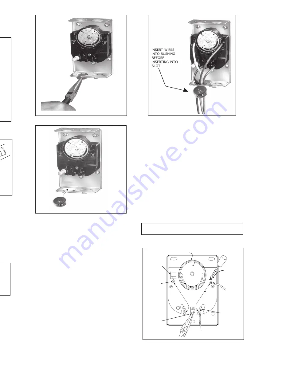
Fig. 5 - Removing slotted knockouts.
Fig. 7 - Closing the strain relief bushing.
Fig. 6 - Insert strain relief bushing.
3. Refer to the following section for type of wiring
connections (standard wire push-in terminals or female
receptacle).
WIRING CONNECTIONS
When connecting cable or conduit to this controller,
use care to avoid strain on the control case.
Connections can be made to standard wire push-in
terminals or female receptacles for 1/4 in. (6.4 mm)
male flag connectors on both the fan and limit
switches (Fig. 8).
FOR STANDARD WIRE PUSH-IN TERMINALS
Connect wires to the terminals as follows:
1. Use Nos. 14,16, or 18 solid wire or Nos. 14 or 16
stranded wire, depending on electrical requirement.
2. Strip insulation from wires the distance shown by
the strip gauge on the controller.
3. Solid wire may be inserted directly into the
terminal holes. If stranded wire is used, insert a small
screwdriver into the slot next to the terminal. Push
screwdriver in and hold while inserting wire into
terminal (Fig. 8). Remove screwdriver. If stranded wire
is solder-dipped, it can be pushed directly into
terminal holes.
FOR FEMALE RECEPTACLES -
It is recommended that the female receptacles be
used for wiring accessory equipment; i.e.,
electronic air cleaner, humidifier, etc.
Connect wires to the receptacles as follows:
1. Use Nos. 14 to 18 size wire, depending on
electrical requirement.
2. Attach 1/4 in. (6.4 mm) male flag connector to
each wire. Two male connectors with leadwires are
supplied.
3. Push male flag connector directly into the
female receptacle. Make sure that the flag is forced
to the bottom of cavity and wire is in the channel
(Fig. 8).
IMPORTANT
Make certain all wires are clear of rotating scaleplate.
Fig. 8 - Location of wiring connections.
69-0117-3
3
2
69-0117-3
Fig. 3 - Rigid bracket mounting requires a hole 13/
16 in. (20.6 mm) diameter for element insertion.
Fig. 4 - Using SUPER TRADELINE adapter.
WIRING
Disconnect power supply before beginning
installation to prevent electrical shock or equipment
damage.
All wiring must comply with local electrical codes and
ordinances or in the absence of local codes with the
National Electrical Code ANSI C1-1981-NFPA 70.
Follow burner or furnace manufacturer’s instructions if
available; otherwise, see Fig. 10 and proceed as
follows.
IMPORTANT
The slotted knockouts on the bottom of the case and
the strain relief bushing are provided to simplify the
installation procedure and to protect the wires.
1. To remove the slotted knockout(s), use a
needlenose pliers as shown in Fig. 5 and pull straight
down.
2. If cable is used, we recommend using a strain relief
bushing in the knockout (Fig. 6). Pass the wires through
bushing before connecting.
SWIVEL MOUNTING
L4064 may also be swivel-mounted. The swivel
bracket requires a 1-9/16 in. (39.7 mm) hole in the
plenum (Fig. 2).
1. Use bracket as a template to mark the location
of mounting holes in plenum. Drill or punch holes
for mounting screws.
2. Fasten the brackets in place with furnished
screws. Start the screws but do not tighten.
3. Insert element tube through bracket, straighten
controller, and fasten. Tighten the mounting screws
securely. It may be necessary to rotate the bracket
to tighten all screws securely.
Fig. 2 - Swivel mounting requires a 1-9/16 in. (39.7
mm) diameter mounting hole for element insertion.
The brass jumper is the breakaway type. It must be
removed when the limit is used in the low voltage
circuit. To remove jumper, break with a needlenose
pliers and remove completely, Once removed, it is
not replaceable. See Fig. 8 for location.
L4064 may be mounted using a rigid bracket. The
rigid bracket requires a hole 13/16 in. (20.6 mm)
diameter for element insertion (Fig. 3).
1. Use bracket as a template to mark the location of
mounting holes in plenum. Drill or punch holes for
mounting screws.
2. Fasten bracket in place with furnished screws.
Tighten the screws securely.
3. Insert element tube through bracket, straighten
controller and fasten by tightening setscrew. Be sure
screw strikes tube frame and does not strike sensing
element.
4. For replacement installations with existing 1 in.
(25.4 mm) diameter hole. SUPER TRADELINE
models are supplied with split steel bushings and wire
snap ring. Follow the instructions below for using the
steel bushing adapter.
STEEL BUSHING ADAPTER
1. Insert one-half of the split steel bushing (Fig. 4),
through the wire ring. It may be necessary to spread
the ring slightly.
2. Insert the other half of the steel bushing into the
ring making sure tabs and ears are at the same ends.
3. Place bushing assembly on element, ear end
first.
4. Holding bushing at seams, push firmly to the
control end of element.
When mounting control on bracket, setscrew must
strike tube frame
not
sensing element to prevent
bypassing the safety limit function.
5. Insert element tube with adapter through bracket,
straighten controller and fasten. Tighten setscrew. Be sure
screw strikes bushing not coiled bimetal sensing element.
RIGID BRACKET MOUNTING
!
WARNING
50
100
150
200
250
ON/OFF
FAN LIMIT
DO NOT ROTATE HOLD
DIAL WHEN SETTING
CAUTION
FAN
LIMIT
PUSH MAN
PULL AUTO
REMOVABLE
BRASS
JUMPER
STANDARD
WIRE PUSH IN
CONNECTORS
(4)
FEMALE
RECEPTACLE FOR
CONNECTION OF
1/4 IN. (6.4 MM)
MALE SPADE
TERMINAL (4)
WIRING GUARD
TO RELEASE
STANDARD WIRE -
PUSH SCREW
DRIVER IN AND
PULL WIRE OUT
STANDARD
WIRE TO
CONTROLLED
EQUIPMENT
LEADWIRE WITH 1/4
IN. (6.4 MM) MALE
SPADE TERMINAL
(FORCE SPADE TO
BOTTOM OF CAVITY)
11,204B
REQUIRE 1-9/16
IN. (39.7 MM)
DIAMETER HOLE
IN PLENUM
FURNACE
PLENUM
32612A SWIVEL
BRACKET
11,220
SETSCREW
FURNACE
PLENUM
RIGID BRACKET
11,205
2696A
TAB
EAR
L4064
HELICAL ELEMENT


