


SPYDER® LON PROGRAMMABLE, VAV/UNITARY CONTROLLERS
63-2685—03
14
All controllers have the terminal arrangements similar to the
examples shown in Fig. 16 and Fig. 17 as described in Table
Table 6 on page 13 and Table 7 on this page.
N
EURON
®
SERVICE PIN
The N
EURON
® Service Pin pushbutton (when pressed)
transmits the Service Message to the network, regardless of
the controller’s current mode of operation (see Fig. 16 and Fig.
CAUTION
Equipment Damage Hazard.
Can cause controller damage or failure.
Do not use any metal object to press the N
EURON
®
Service Pin. Use a plastic rod or wood device (such as
a pencil with the lead broken off) to press the pin. Using
a metal object can damage the circuitry of the
controller.
LONWORKS BUS CONVENIENCE JACK
The L
ON
W
ORKS
Bus connection is provided by plugging the
Serial L
ON
T
ALK
®
Adapter (SLTA) connector into the
L
ON
W
ORKS
® Bus Jack (see Fig. 16 and Fig. 17).
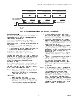
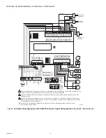
Fig. 16. Controller Terminal Connections, N
EURON
® Service
Pin, & LONWORKS® Bus Jack for the PUL6438S,
PVL6436AS, and PVL6438NS (PVL6438NS shown).
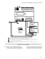
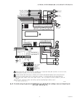
Fig. 17. Controller terminal connections, NEURON®
Service Pin and LONWORKS® Bus Jack for the PUL1012S,
PUL4024S, PVL0000AS, PVL4022AS, and PVL4024NS
(PVL4024NS shown).
Wiring Applications (Examples)
Fig. 18–Fig. 24, beginning on page 15, illustrate controller
wiring for the following configurations.
• Typical controller wiring for VAV application using the TR23
Wall Module and a C7770A Air Temperature Sensor (see
• Typical controller wiring for VAV application with staged
reheat (see Fig. 19 on page 16).
• Typical controller wiring for PWM reheat and PWM
peripheral heat valve actuator (see Fig. 20 on page 17).
• Typical controller wiring for AHU application (see Fig. 21 on
• Typical controller wiring for 4 to 20 mA enthalpy sensors
and digital inputs (see Fig. 22 on page 19).
• Typical controller wiring for 4 to 20 mA heating, cooling, and
model ML6161 floating motor control (see Fig. 23 on
• Typical controller wiring for a pneumatic transducer, model
RP7517B (see Fig. 24 on page 21).
LONWORKS
®
BUS JACK
(LABELLED SRV JCK)
NEURON
®
SERVICE PIN
(LABELLED SRV PIN)
TERMINALS 1-8
TERMINALS 9-20
TERMINALS 21-40
AO-1 COM AO-2 AO-3 COM
UI-1 COM UI-2 UI-3 COM UI-4 UI-5 COM UI-6
DI-1 DI-2 COM DI-3
20V DC
DI-4
NET
-2
NET
-1
SHLD
EGND
24 V
AC
24V
AC COM
DO-1
COM
DO-2
DO-3 DO-4
DO-5
COM
DO-6 COM
1 2 3 4 5 6 7 8
1
0
9
2 3 4 5 6 7 8 0
9
1
1 1 1 1 1 1 1 1 2
1
1 2 3 4 5 6 7 8 0
9
2
2 2
2 2 2 2 2 2 3
3
1 2 3 4 5 6 7 8 0
9
3
3
3
3 3
3 3
3 4
M23561B
DO-7 DO-8 COM
SBUS1 SBUS2
M28650
1 1 1 1 1 1 1 2 2 2 2 2
3 4 5 6 7 8 9 0 1 2 3 4
UI-4
COM
UI-3
UI-2
COM
UI-1*
AO-2
COM
AO-1
COM
DO-2
DO-1
1 1
1 2 3 4 5 6 7 8 9 0 1 2
COM
DO-4
COM
DO-3
NET
-2
NE1-2
S-BUS 2
S-BUS 1
20VDC
EGND
24V
AC COM
24V
AC
TERMINALS 13-24
TERMINALS 1-12
LONWORKS ® BUS JACK (LABELLED SRV JACK)
NEURON® SERVICE PIN (LABELLED SRV PIN)


