


S8700B,D-F,J-M DIRECT SPARK IGNITION CONTROLS
5
69-1299
Resetting S8700 After Safety Lockout
After completing the normal ignition sequence, without
proving main flame, the S8700 models will shut off the
spark and gas flow and go into lockout. S8700B,D,J,K
will stay in lockout until the call for heat is removed and
restored. S8700E,F,L,M will stay in lockout for 60 min-
utes, then another ignition sequence will start. If the call
for heat is interrupted then restored, all S8700 models
will start a new ignition sequence.
To reset the system at any time:
Adjust the temperature control setting to below the room
temperature, wait five seconds, and move the tempera-
ture control setting up to call for heat or remove 24V
power and reapply. Normal ignition should occur as
described in the Start System section.
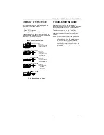
CHECKOUT
Start the system and observe operation through at least
two complete cycles to make certain all controls and the
appliance are operating safely.
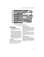
Sequence of Operation
The S8700 control performs the following basic
functions:
— Supplies power to the electronic pulse-generator
circuit for the spark igniter. Allows up to the specified
trial for ignition and one or three trials before system
safety lockout occurs (see Table 1 and Table 3).
— Senses the burner flame(s) for safe lighting.
— Shuts off spark after burner is lit.
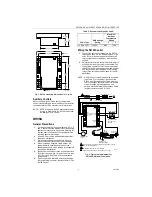
The S8700 is powered by a 24V transformer and is
activated when the temperature control calls for heat.
See Fig. 4 or 5, depending on model.
Operation is as follows:
When the S8700 is activated by the call for heat from
the temperature control, the S8700 performs a safe-
start check that determines proper operation of the
control before beginning the normal sequence of opera-
tion. This check also determines if a flame signal is
being sensed. If flame is sensed or the control identifies
any internal failure, the S8700 will go to lockout (LED
steady on). Once the safe start check operation passes,
the S8700 turns on the spark circuit and at the same
time energizes the gas control main valves and allows
gas to flow to the main burner.
Sparking continues until the trial for ignition ends,
unless the main burner lights and is sensed as sufficient
to shut off the spark and allow normal operation.
If the main burner lights, a flame sensing circuit is com-
pleted through the flame to the burner head and back to
the S8700 GND (Burner) terminal. This current flow sets
the trial for ignition timer to the reset (normal) condition
and interrupts the spark ignition circuit. Should the
current flow be interrupted, i.e., flame out condition, the
spark will be re-initiated immediately and a normal trial
for ignition will occur. If the main burner lights and
proves, a normal run will occur. If the main burner does
not light and prove, the S8700 goes into lockout.
The S8700 keeps the gas control main valve open as
long as there is a call for heat and sufficient flame
current through the flame sensing circuit. If, however,
the trial for ignition period ends before the main burner
lights or the main flame generates enough flame cur-
rent, the system goes into safety lockout
(S8700B,D,J,K) or between trial purge (S8700E,F,
L or M).
When the system goes into safety lockout, power to the
spark generator is interrupted, the power to the gas
valve is interrupted, the alarm circuit is completed and
the LED is steady on. The system stays locked out until
it is reset by moving the temperature control setpoint to
below the room temperature, no call for heat, for five
seconds. The system can be re-energized by moving
the temperature control setpoint 5
°
F (3
°
C) above the
room temperature or removing 24V power to the control
then reapplying.
Note:
S8700E,F, L, M models automatically reset
from lockout after one hour if the call for heat is
still present. A normal ignition sequence will be
initiated.
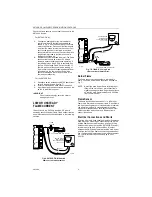
SERVICE
WARNING
High Voltage Hazard.
Shock can cause personal injury.
To prevent electric shock, do not allow fingers to
touch the stripped end of the jumper or the
spark terminal.
IMPORTANT
— Only persons trained and experienced in DSI
systems should service this equipment.
— Always de-energize the system for at least five
seconds before recycling for further tests.
— Always turn off the gas supply before performing
ignition checks.
— S8700 control cannot be repaired. If the
troubleshooting procedure indicates a malfunction in
the S8700, it must be replaced.
— The following service procedures are for the S8700
and basic DSI systems. On all installations, refer to
the appliance manufacturer’s service instructions.
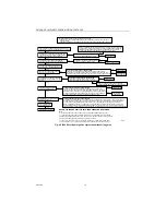
Preliminary Check
The following checks should be made before trouble-
shooting the system:
— Check for power to the heating appliance and the
S8700. Voltage to the control should be between
20.5 and 28.5 Vac, when in run mode.
— Make certain that the manual shut-off valve in the
supply line and the gas cock knob on the
combination gas control valve are open.
— Check the ignition cable for signs of damage or cut
insulation, exposed wires or loose connections.
Repair or replace as necessary.
— Make certain that all wiring connections are clean
and tight.
Summary of Contents for S8700 Series
Page 11: ...11 69 1299 ...


