


S8700B,D-F,J-M DIRECT SPARK IGNITION CONTROLS
69-1299
2
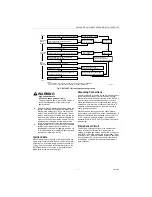
Frequent Cycling
The S8700 is designed to cycle three to four times each
hour during the heating season. Year-round applica-
tions and applications with more frequent cycling rates
can wear out the controls more quickly than normal
operation. Perform monthly system checks to make
sure the system operates properly.
Water or Steam Cleaning
If a control gets wet, replace it. If the appliance is likely
to be cleaned with water or steam, cover the control and
wiring to protect them from water or steam flow. Mount
the control high enough above the floor so it does not
get wet during normal cleaning procedures.
High Humidity or Dripping Water
Dripping water can cause the control to fail. Never
install an appliance where water can drip on the control.
In addition, high ambient humidity can cause the control
to corrode and fail. If the appliance is in a humid atmo-
sphere, make sure air circulation around the control is
adequate to prevent condensation. Also, regularly
check out the system.
IMPORTANT
Always install a splash cover to protect the
control from water damage.
Corrosive Chemicals
Corrosive chemicals can attack the control, eventually
causing a failure. If chemicals are used for routine
cleaning, avoid contact with the control. Where
chemicals are suspended in air, as in some industrial or
agricultural applications, protect the control with an
enclosure.
Dust or Grease Accumulation
Heavy accumulations of dust or grease can cause the
control to malfunction. Where dust or grease can be a
problem, provide covers for the control to limit
contamination.
Heat
Excessively high temperatures can damage the control.
Make sure the maximum ambient temperature at the
control does not exceed the rating of the control, see
Specifications section. If the appliance operates at very
high temperatures, use insulation, shielding and air
circulation, as necessary, to protect the control. Proper
insulation or shielding should be provided by the
appliance manufacturer; verify proper air circulation is
maintained when the appliance is installed.
System Requirements
S8700 system requirements:
— Q347A Spark Igniter and Q354A Flame Sensor, or a
Q366 with separate spark igniter and flame sensor
mounted on a common bracket. (Equivalent ignition
hardware may be used.)
— Honeywell VR8205 Gas Valve (or equivalent)
designed for DSI applications. Valve loads must be
within the range listed in the Specifications section.
INSTALLATION
When Installing this Product…
1.
Read these instructions carefully. Failure to follow
them could damage the product or cause a
hazardous condition.
2.
Check the ratings given in the instructions and on
the product to make sure it is suitable for your
application.
3.
The installer must be a trained, experienced
service technician.
4.
After installation is complete, check out system
operation.
WARNING
Fire or Explosion Hazard.
Gas leaks can cause property damage,
severe injury or death
Always turn off gas supply before installing a
new gas control.
Be sure to conduct a gas leak test after installing
the control.
CAUTION
Electric Shock Hazard.
Power supply can cause personal injury or
equipment damage.
Disconnect power supply before installation.
IMPORTANT
If this is a replacement application, follow the
appliance manufacturer’s instructions, if
available.
The manufacturer usually provides wiring dia-
grams, start-up and checkout instructions and
service procedures for their system. If the
manufacturer’s instructions are not available,
use these instructions as a general guide.
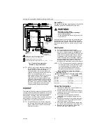
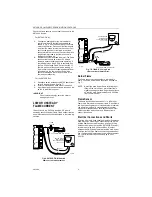
MOUNTING
S8700 Control
Select a location within 6 ft (1.8m) of the burner that
permits a direct cable route to the spark igniter terminal.
Ready access to the S8700 terminals is necessary for
wiring and servicing. Do not exceed the ambient tem-
perature rating given in the Specifications section.
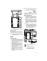
To mount the S8700:
1.
Mount the S8700 in any position. See Fig. 1 for
mounting dimensions.
2.
Use No. 6-32 machine screws or 1 in. No. 8 sheet
metal screws for fastening.
3.
Fasten the screws securely.
Summary of Contents for S8700 Series
Page 11: ...11 69 1299 ...


