


P7810C,D PRESSURETROL
®
CONTROLLER
65-0235—1
7
LED Display
The yellow light emitting diode (LED) is always lighted with
power applied to the P7810 Pressuretrol® Controller. The
microprocessor changes the brightness of the yellow LED to
indicate normal operation, turns the green LED on and off to
indicate call for heat status, and flashes both LED to indicate
a fault.
NOTE:
The term “flashing” means on/off/on/off for the green
LED and bright/dim/bright/dim for the yellow LED.
Standard LED signals are:
a. Yellow LED flashing, green LED off: P7810 is operating
normally, there is no call for heat.
b. Yellow LED flashing, green LED on: P7810 is operating
normally; there is a call for heat.
c. Yellow and green LED flashing alternately (yellow is
bright when green is off; yellow is dim when green is
on): P7810 is in a safety lockout due to pressure
exceeding limit setpoint setting.
d. Yellow and green LED flashing at the same time:(yellow
is bright when green is on; yellow is dim when green is
off): P7810 is in a safety lockout due to an internal fault,
possibly due to supply side of limits circuit not being
connected to the COM terminal.
CHECKOUT
WARNING
Electrical Shock Hazard.
Can cause serious injury or death.
Live voltage is present at the P7810 and all controller
circuits. Use extreme care during checkout.
IMPORTANT
1. Do not put the system in service until all applicable
tests described in the Checkout section of the
instructions for the primary safety control and any
additional tests required by the burner or boiler
manufacturer are satisfactorily completed.
2. Close all manual fuel shutoff valves when trouble
occurs.
Checkout
WARNING
Explosion Hazard.
Can cause serious injury or death.
This checkout procedure disables the Safety High
Limit function.
After installation and wiring, check out the P7810
Pressuretrol® Controller with the system in operation.
1. Allow the system to stabilize.
2. Observe the operation of the P7810 Pressuretrol®
Controller while raising and lowering the setpoint.
Pressure increases when the setpoint is increased and
decreases when the setpoint is decreased.
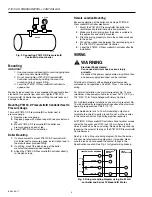
Check the make and break points of the P7810 Pressuretrol®
Controller. If they do not agree with a separate, accurately
calibrated pressure gauge, make a slight adjustment
according to the scale. Use accurate pressure testing
equipment when checking out the P7810 Pressuretrol®
Controller. Do not rely on inexpensive gauges. The P7810
Pressuretrol® Controller is carefully calibrated at the factory.
Test the P7810 Pressuretrol® Controller as follows:
NOTE:
Make sure the P7810 is operating properly by
checking the LED indicators. If the P7810 LED
indicate a lockout condition, press the manual reset
button.
NOTE:
This procedure simulates pressure changes using
dial setpoint adjustments. Make dial adjustments
very slowly because of filtering delays within the
P7810C,D. Inaccuracy can result if dial adjustments
are not made very slowly. To observe actual
P7810C,D control accuracy, set the dials to normal
operating values. Compare the dial settings to the
boiler pressure readings where P7810 actions occur.
To check the control setpoint of the P7810C,D:
1. Note the boiler pressure by checking the boiler
pressure gauge. To properly perform these tests, the
boiler pressure should be near the middle of the P7810
pressure range.
2. Turn the P7810 limit setpoint dial fully clockwise to
make sure that this limit does not interfere during steps
4 and 5. This setting must return to the proper operating
position when returning the system to normal operation.
3. Check the control setpoint and control differential.
4. Set the control differential to the center of its range.
5. Turn the control setpoint dial fully counterclockwise and
make sure the P7810 control circuit is open and the
green LED is off (no call for heat).
6. Read the boiler pressure gauge and add this number to
the control differential setting.
7. Turn the control setpoint dial slowly clockwise and make
sure the control circuit closes and the P7810 indicates
a call for heat (green LED on) when the P7810 control
setpoint passes through the value determined in step 6.
8. Turn the control setpoint dial slowly counterclockwise
and make sure the control circuit opens and the P7810
no longer indicates a call for heat (green LED off) when
the control setpoint passes through the boiler pressure
gauge value.
Check the modulation setpoint and modulation range of the
P7810C as follows:
1. Set the P7810 modulation range dial to the center of
the range.
2. Turn the modulation setpoint dial fully clockwise and
make sure the firing rate motor travels to the fully open
position (boiler is firing).
3. Turn the modulation setpoint dial slowly
counterclockwise and make sure the firing rate motor
starts moving toward the closed position when the
modulation setpoint passes through the boiler pressure
gauge value. (Alternately, make sure the current starts
decreasing toward 4 mA.)
4. Determine the pressure point at which minimum
modulation output will occur by checking the boiler
pressure gauge and subtracting the modulation range
dial setting (at midpoint).