16
LCD-160 Manual —
P/N 51850:D2 10/07/2016
Section 6: Wiring
This section explains how to wire the LCD-160 for communication, power, and security.
6.1 Overview
Complete all mounting procedures and check all wiring before applying power. The terminal block
and pin connections are illustrated in Figure 3.1. Electrical connections are listed below and are
detailed in the following paragraphs:
•
TB1
- Remote Data Port (RDP) interface connection.
•
TB2
- Power Supply connection
•
J1
- Key Switch connection
•
J4
- NUP Port (Future use)
Power-limited (Class 2) wiring must remain separated from non-power-limited wiring by at least
0.25 in. (6.4 mm), and must enter an enclosure through different knockouts. Install tie wraps and
adhesive squares to secure the wiring.
!
WARNING:
REMOVE ALL POWER SOURCES TO EQUIPMENT WHILE CONNECTING ELECTRICAL
COMPONENTS. LEAVE THE EXTERNAL, MAIN POWER BREAKER OFF UNTIL INSTALLATION OF
THE ENTIRE SYSTEM IS COMPLETE.
!
WARNING:
SEVERAL SOURCES OF POWER CAN BE CONNECTED TO THE CONTROL PANEL. BEFORE
SERVICING THE CONTROL PANEL, DISCONNECT ALL SOURCES OF INPUT POWER
INCLUDING
THE BATTERY
. WHILE ENERGIZED, THE CONTROL PANEL AND ASSOCIATED EQUIPMENT CAN
BE DAMAGED BY REMOVING AND/OR INSERTING CARDS, MODULES, OR INTERCONNECTING
CABLES.
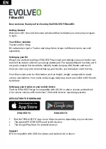
Power-
limited
(Class 2)
circuits
Nonpower-
limited
circuits
Power-limited (Class 2) circuits
Figure 6.1 Typical Wiring for UL Power-limited Wiring Requirements
(LCD-160 and XPIQ mounted in CAB-4 series backbox.)
XPIQ
In this illustration, the
LCD-160 is powered by a
remote power supply.
LCD-160