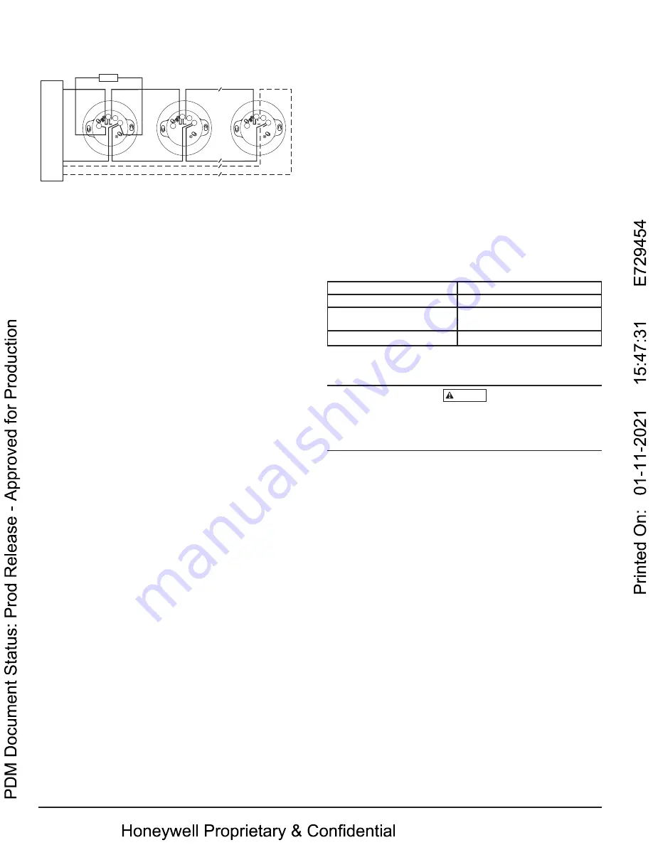
FIGURE 2. WIRING DIAGRAM
2
3
1
2
3
3
1
2
1
(–)
(+)
+
-
UL Listed Compatib
le
Control P
anel
CAUTION: Do not loop wire under
terminal 1 or 2. Break wire run to
supervise connections.
CLASS A OPTIONAL WIRING
Remote
Annunciator
(–)
(+)
RA
+
–
+
RA
+
–
+
RA
+
–
+
C0129-10
TAMPER-RESISTANCE
Intelligent photoelectric smoke sensors include a tamper-resistant capability
that prevents their removal from the base without the use of a tool. Refer to
the base manual for details on making use of this capability.
TESTING
Before testing, notify the proper authorities that the system is undergoing
maintenance, and will temporarily be out of service. Disable the system to
prevent unwanted alarms.
All sensors must be tested after installation and periodically thereafter. Test-
ing methods must satisfy the Authority Having Jurisdiction (AHJ). Sensors
offer maximum performance when tested and maintained in compliance with
NFPA 72.
The sensor can be self-tested or manually tested as described below.
SELF-TEST TESTING
A. Functional and Smoke-Entry Tests
The Notifier system with Self-Test sensors can carry out both functional tests
and smoke entry tests using the Self-Test function. The Self-Test sensor gener-
ates a controlled amount of smoke which is directed into the sensing cham-
ber, testing the optical chambers response to real smoke. It also measures the
amount of time it takes to evacuate smoke from the chamber to determine if
there is anything masking smoke entry points on the sensor.
1. Use the associated app and gateway (see Connected Life Safety Services
guides).
2. Initiate self-test from app. Wait at least 30 seconds before communicating
with the device; wait at least 90 seconds before moving or re-cycling.
3. Take appropriate action based on the outcome of the testing results. If it
has failed, the device should be considered for cleaning or replacement.
NOTE: For safer testing the fire system can remain active while Self-Test is in
progress. The process will delay any alarm input signal from the SLC includ-
ing pull stations, input modules and other sensors (not undergoing Self-Test)
by a maximum of 30 seconds. Multiple loops and panels may be tested simul-
taneously.
B. VISUAL INSPECTION
This sensor contains a wireless beacon (only active during Self-Test process)
which is designed to communicate with the Honeywell Connected Life Safety
Services app in order to prove the successful completion of the visual inspec-
tion of any Self-Test sensor.
1. A range of Self-Test sensors can be placed into a beaconing mode from the
supporting app.
2. The App will display all selected Self-Test devices in range of your smart
phone and will place the device with the strongest signal at the top your
App display. The App will also provide details on the device address, loca-
tion and label. (For further details on the associated app and gateway see
Connected Life Safety Services guides).
3. Once the sensor is in beaconing range of your smart phone, you must
verify the completion of the visual inspection of the sensor via the App
(recording any remedial action required if necessary). Criteria for success-
fully passing the visual inspections is available to review in the relevant
section of NFPA 72 guidance.
4. If the label of the self-test sensor is incorrect, you can update this on the
App (subject to holding the relevant user licence), which will upload it to
the system when you pair the device with the Connected Life Safety Ser-
vices gateway on completion of the visual inspection.
SELF-TEST TOKENS
If your license requires Self-Test tokens in order to activate the Self-Test pro-
cess, please refer to your Connected Life Safety Services guides in order to
purchase the required volume of tokens to complete testing on your project.
MANUAL TESTING
A. Functional: Magnet Test (P/N M02-04-01 or M02-09-00)
This sensor can be functionally tested with a test magnet. The test magnet
electronically simulates smoke in the sensing chamber, testing the sensor elec-
tronics and connections to the control panel.
1. Hold the test magnet in the magnet test area as shown in Figure 3.
2. The sensor should alarm the panel.
Two LEDs on the sensor are controlled by the panel to indicate sensor status.
Coded signals, transmitted from the panel, can cause the LEDs to blink, latch
on, or latch off. Refer to the control panel technical documentation for sensor
LED status operation and expected delay to alarm.
B. Smoke Entry
Sensitivity readings are available through the FACP. Refer to the manufac-
turer’s published instructions for proper use.
Additionally, canned aerosol simulated smoke (canned smoke agent) may be
used for smoke entry testing of the smoke detector. Tested and approved aero-
sol smoke products include:
Manufacturer
Model
HSI Fire and Safety
25S, 30S (PURCHECK)
SDi
SMOKE CENTURIAN, SOLO A10,
SMOKESABRE, TRUTEST
No Climb
TESTIFIRE 2000
When used properly, the canned smoke agent will cause the smoke detec-
tor to go into alarm. Refer to the manufacturer’s published instructions for
proper use of the canned smoke agent.
CAUTION
Canned aerosol simulated smoke (canned smoke agent) formulas will vary
by manufacturer. Misuse or overuse of these products may have long term
adverse effects on the smoke detector. Consult the canned smoke agent manu-
facturer’s published instructions for any further warnings or caution statements.
A sensor that fails any of these tests may need to be cleaned as described
under CLEANING, and retested.
When testing is complete, restore the system to normal operation and notify
the proper authorities that the system is back in operation.
CLEANING
Before removing the detector, notify the proper authorities that the smoke
detector system is undergoing maintenance and will be temporarily out of
service. Disable the zone or system undergoing maintenance to prevent un-
wanted alarms.
1. Remove the sensor to be cleaned from the system.
2. Remove the sensor cover by pressing firmly on each of the four removal
tabs that hold the cover in place. (See Figure 4.)
3. Vacuum the screen carefully without removing it. If further cleaning is
required continue with Step 4, otherwise skip to Step 7.
4. Remove the chamber cover/screen assembly by pulling it straight out.
5. Use a vacuum cleaner or compressed air to remove dust and debris from
the sensing chamber.
6. Reinstall the chamber cover/screen assembly by sliding the edge over the
sensing chamber. Turn until it is firmly in place.
7. Replace the cover using the LEDs to align the cover and then gently push-
ing it until it locks into place.
8. Reinstall the detector.
9. Test the detector as described in TESTING.
10. Reconnect disabled circuits.
11. Notify the proper authorities that the system is back on line.
SPECIAL NOTE REGARDING SMOKE DETECTOR GUARDS
Smoke detectors are not to be used with detector guards unless the combina-
tion has been evaluated and found suitable for that purpose.
2
I56-6782-000
1/6/2021


