background image

AM-1224 

Installation and programming manual 

PAGINA -


 21 

AM-1224_manu 

Doc. M-124.1-AM1224-ENG Rev A.1 

NOTIFIER ITALIA


T

T

i

i

m

m

i

i

n

n

g

g


In this sub menu are programmed alarm outputs delay, the delay time to check sensors alarms, silence inhibitio, 
etc. 
 

“Alarm output”


By pressing the Enter key   activates the function of editing. 
Input data with arrow keys 



 or from keyboard, than press enter key   to confirm the configuration. 

Sounder delay time is active only in case of alarm if the immediate activation of outputs in the menu 
exclusions is excluded. 

 
From “Timing\ Usc.all “ press arrow dx. key 

4

 to enable verification on lines. 


“Verif. Enabled.” 

allows the control panel to verify all lines enabled. 


SILENCE INIBITION TEMPORIZATION

 is the time during which output silence operation is not allowed 

after an alarm. 


From menù “Prog\Syst\Timings” press arrow dx. key 

4

 to configure function timings 

“Sign. Sil.”

 .


By pressing the Enter key   activates the function of editing. Input data with arrow keys 



than press enter 

key   to confirm the configuration. 


Timings are expressed in 
seconds, from a minimum of 0 
sec. to a max. of  255 sec.


Sounder

” delay are expressed in seconds, 

from a minimum of 0 sec. to a max. of  600 sec. 

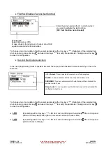
By pressing the Enter key   activates the function of 
editing.  
Con i tasti freccia 



selezionare  la voce che si 

desidera . 

Press enter key   to confirm the configuration .


Summary of Contents for Notifier AM12-24

Page 1: ... AM12 24 Conventional fire panel ...

Page 2: ...FACE DESCRIPTION 14 Keyboard operation for the data input in the programming file 14 Stand by condition 15 RECOMMENDED SEQUENCE FOR CONTOL PANEL CONFIGURATION 16 Display in Zone Alarm condition 17 Display in Zone Fault condition 17 Display in System Trouble condition 18 Display in Zone Test condition 19 Displaying lists devices and areas excluded 19 CONFIGURATION MENÙ 20 System menù 20 Expansion 2...

Page 3: ...lease consult NOTIFIER Technical Service for any doubt This system like all solid state components may be damaged by induced electrostatic voltages handles the boards keeping them among the edges and avoid to touch the electronic components An appropriate earthing connection ensures in any case a sensitivity reduction to disturbances Please consult NOTIFIER Technical Service if you cannot solve in...

Page 4: ...e panel is compatible with all conventional field devices available by Notifier Italia M Ma ai in n f fe ea at tu ur re es s User interface Software in one language Italian as default replaceable by PC 12 detection conventional lines expandable up to 24 with one option card Up to 25 conventional detectors per line Optional 8 relay 8 OC transistor outputs card On board general Alarm and general Fau...

Page 5: ...r 12 V 18 Ah Dimensions 181 b x 77 p x 167 h The followings are thresholds for faults indication on the Battery charger section Battery exaust 21 5 Vdc Difference between batteries thresholds 3 4Vdc Battery cut out thresholds 20Vdc Current from battery in standby condition without mains no 230 Vac 180 mA 12 lines with End of Line resistor no external loads display OFF Current from battery in Alarm...

Page 6: ...o the panel using knock out holes running them along the cabinet internal side providing sufficient length especially for those connected to the CNAL terminal block 230 Vac wire power supply must be fixed inside of the control panel For the 230 Vac wire power supply must be interrupted by an external shut down switch For installation in a corner it is necessary to have a distance of 280mm to let t...

Page 7: ...Power supply connection shall be made in the following sequence 1 Open the 230 Vac power supply general switch 2 Disconnect terminal block CNAL from the control panel 3 Connect the power supply cable 4 Reconnect terminal block CNAL 5 Close the mains general switch 6 Install and connect batteries as specified in this manual 7 Close the control panel D De et te ec ct ti io on n L Li in ne es s Detec...

Page 8: ...User output fuse Fast glass F1AL F2 Sounder output fuse Fast glass F1AL F3 Battery output fuse Resettable Fuse MFR250 F4 Mains 230Vac Fuse Fast glass F1AL L Li in ne es s c co on nn ne ec ct ti io on ns s EN54 EN54 2 8 8 Fault Output The general Fault relay is normally energized In Fault condition it will be de energized Note To comply the EN 54 2 7 7 don t connect on this output remote warning de...

Page 9: ...esistance The output is protected by a 1 A fuse M Ma ai in n B Bo oa ar rd d Note The polarity shown on CN0 5 and CN0 6 aren t in alarm condition CN0 6 CN0 5 47K Polarized sounder Not polarized sounder 47K Mains Terminal block F1AL 230V fuse Resettable fuse MFR250 Power ON LED Battery 2x12V CN Terminal block CN Terminal block Front panel board terminal block Panel reset button JDSP Groun fault det...

Page 10: ...End of Line resistor 47K 5 7 TX 8 RX 9 GND RS232 serial interface input used for UPLOAD 10 11 24Vdc 1A User 12 13 GND User Protected with 1A Fuse Total current 1A Sounder User 14 Auxiliary input External power supply Fault indication 15 Auxiliary input level 2 access 16 Auxiliary input Evacuation 17 Auxiliary input Technical Alarm End of Line resistor 2k7 ohm 5 1 4W Terminal CN1 Description Note 1...

Page 11: ... CN2 Description Note 1 Line 13 GND 2 Line 14 GND 3 Line 15 GND 4 Line 16 GND 5 Line 17 GND 6 Line 18 GND 7 Line 19 GND 8 Line 20 GND 9 Line 21 GND 10 Line 22 GND 11 Line 23 GND 12 Line 24 GND 13 Line 13 14 Line 14 15 Line 15 16 Line 16 17 Line 17 18 Line 18 19 Line 19 20 Line 20 21 Line 21 22 Line 22 23 Line 23 24 Line 24 End of Line resistor 2k7 ohm 5 1 4W CN2 terminal block Main board terminal ...

Page 12: ...U04 Max 2A 30Vcc resistive load Contact NO NC selectable by jumper 9 Output OC1 U09 10 Output OC 2 U10 11 Output OC 3 U11 12 Output OC 4 U12 Open collector Max Current 30mA 13 Relay 5 Com 14 Relay 5 NO NC J1 U05 15 Relay 6 Com 16 Relay 6 NO NC J3 U06 17 Relay 7 Com 18 Relay 7 NO NC J5 U07 19 Relay 8 Com 20 Relay 8 NA NC J7 U08 Max 2A 30Vcc resistive load Contact NO NC selectable by jumper 21 Outpu...

Page 13: ...NA 11 AM 1224_manu Doc M 124 1 AM1224 ENG Rev A 1 NOTIFIER ITALIA D Di is sp pl la ay y b bo oa ar rd d F Fr ro on nt t P Pa an ne el l J1 Programmation key jumper Default N O Front panel indications LEDs Keyboard connector Base board terminal block ...

Page 14: ...ivated in case of alarm the first pressure of this key will de activate the sounder output A second pressure with the same condition will reactivate the sounders RESET the pressure of this key delete the memory of alarms and points troubles present at the moment De activate the sounders and turn off the lighted signals fo the detectors in alarm To do this procedure it is necessary to know the pass...

Page 15: ... exclusion in the control panel We are referig to all the exclusions that could be done in the exclusion menù WALK TEST IN PROGESS Yellow Lighted when the test is in progress POWER OK Green Fix lighted when the control panel is powered FAULTS Yellow It is flashing if there is almost a trouble of any kind that has not been identified yet It remains lighted if all the trouble have been identified SY...

Page 16: ... The selected field can be changed entering in editing mode with return key According to the type of data we have different editing Text strings CBE text description for lines or zone 4 new functioning key are displayed F1 capital small selection F2 letters numbers symbols selection F3 insertion F4 delete with the keys it is possible to select the type for the current position with the keys 4 it i...

Page 17: ...e operation of the keyboard for data entry See utility menù Function associated to the key F3 In this case the pressure of the Key F3 allow the entry in the Exclusion menù See paragraph description of the operation of the keyboard for data entry See exclusion menù Function associated to the key F4 In this case the pressure of the Key F4 allow the entry in the Test menù See paragraph description of...

Page 18: ...Menù select System than Expansion to enable the optional board From te menu Program select Detector line press enter key by function key F1 or F2 than select the line to enable the reception of alarm from the field Select Enable with key arrow and press enter key Again using the arrow keys to selec YES than press enter key to confirm configuration Then assign a name to a line see page 24 and assig...

Page 19: ... alarm Display in Zone Fault condition The followin screen show the display in zone fault condition Troubles event are displayed by zone association Using Arrow keys is possible to browse the list of Zone in Trouble condition Line in alarm Text programmed For the zone name First zone in alarm Text programmed For the zone name Last zone in alarm Text programmed for the zone name Event Date and hour...

Page 20: ...line name and type of fault With escape or leaving the keyboard with no operation for more than 15 seconds the display come back to Zone Fault list automatically Display in System Trouble condition Fault events related to panel are defined as System Faults for example low battery voltage Mains loss etc System faults are displayed indicating the type of fault Line in Fault Text programmed For the L...

Page 21: ...ying lists devices and areas excluded From the main screen by pressing the function key F3 is possible to access to following menù the user selecting the Display access to the following screen Select with arrow keys exclusion to display Than press enter to confirm selection The display will show the first item excluded with arrow keys is possible to brose the listo f item excluded Date Time of the...

Page 22: ...ode described above in the section describing the keyboard data entry operation The following menu will dispalyed System menù Selecting sub menù System is possible to configure the general parameters valid for the control panel see following picture E Ex xp pa an ns si io on n This function enable the optional 24 detector line expansion board See paragraph System menù See paragraph Detector line S...

Page 23: ...ow dx key 4 to enable verification on lines Verif Enabled allows the control panel to verify all lines enabled SILENCE INIBITION TEMPORIZATION is the time during which output silence operation is not allowed after an alarm From menù Prog Syst Timings press arrow dx key 4 to configure function timings Sign Sil By pressing the Enter key activates the function of editing Input data with arrow keys th...

Page 24: ... d S Sy ys st te em m To enter system name press enter key To enter system name see the editing mode described above in the section describing the keyboard data entry operation At the and press enter key to store the text This feature allows you to change the password for the three levels of access Each password consists of 5 numeric characters The numeric characters are available for change your ...

Page 25: ... o Second folder or programmation folder Z Zo on ne e a as ss so oc ci ia at ti io on n Line numer Editable label max 16 characters _ Line disabled P Line Enabled Press F1 to configure previous line Press F2 to configure next line Number of zone assigned To assign the number of Zone for the selected line press enter key and use arrow keys to change the number of zone Finally press enter key to con...

Page 26: ...nabled After this procedure which takes about 20s if the alarm is still present is validated Line number Configure Present YES to detect reports from Aux power supply fault input Press F1 to configure previous input Press F2 to configure next input Configure Present YES to enable input Level acess 2 Press F1 to configure previous input Press F2 to configure next input Configure Present YES to enab...

Page 27: ... keys F1 or F2 o o Second folder or program Folder C CB BE E e eq qu ua at ti io on n S Si il le en nc ce e Programmable label max 16 characters CBE equation Press enter key to modify to CBE To enter data see the editing mode finishing press enter key to confirm the configuration Output number Type disabled no activation Type CBE output activation from CBE Type Alarm uactive output in alarm condit...

Page 28: ...r that the control panel AM12 24 is prepared for functionality Up Download When the upload and download of data from PC has been completed the control panel displays the following message Transfer complete To extit from Up Download function use escape key Clear configurations Selecting this function the display will show as follow To erase all data stored in the non volatile memory system user mus...

Page 29: ...tion The following menù is displayed Date and Time This function allows the programming time and date of the control panel To change one or more data in the programming line Date and Time use arrow keys 4 to select the field to change characters of the selected field are in white on black background use arrow keys To store the configuration press enter key Date configuration Day of the week config...

Page 30: ...ory log o o V Vi ie ew w a an nd d p pr ri in nt t This function allows the visualization on the display of the historical archives o o R Re es se et t Selecting Clear history log function the following will displayed This function allows the visualization and printing of events stored in the history log The Reset function allow the complete cancellation of the events memorized in the historical a...

Page 31: ...l show of default To select the next output use the function keys See V Vi is su ua al li iz za at ti io on n o of f l li in ne e s st ta at tu us s p pa ar ra ag gr ra ap ph h Linea number Linea name Linea status Output number Output name Output status With arrow key user can modify the output status Active ON Deactivated OFF See V Vi is su ua al li iz za at ti io on n o of f o ou ut tp pu ut t s...

Page 32: ...ll lo ow ws s t th he e m ma ai in nt te en na an nc ce e p pe er rs so on nn ne el l o of f t th he e c co on nt tr ro ol l p pa an ne el l t to o d di is sp pl la ay y t th he e i in ns st ta al ll le ed d f fi ir rm mw wa ar re e v ve er rs si io on n s se ee e e ex xa am mp pl le e i in n f fi ig g b be el lo ow w M MA AS SK K M ME EN NU U By using F3 function key is possible to enter in the m...

Page 33: ...played In this submenu you can change the state included excluded for the listed items Detector line The display show the first detector line of default To change line use function keys When a detector is excluded the control panel can not receive the alarm and trouble signal from it To exclude a line select it with the function keys F1 or F2 Once you select a line press the Enter key and with arr...

Page 34: ...lect it with the function keys Once you select a line press the Enter key and with arrow key select YES then press enter key to confirm the configuration This function allow the exclusion of the sounder output CN0 5 and CN0 6 on the main board When a zone is excluded the control panel can not receive the alarm and trouble signal from all lines that belong to the zone To exclude a zone select it wi...

Page 35: ...sistance staff to test the system To enter the password see the editing mode described above in the section describing the keyboard data entry operation The following menù will displayed Zone This function allows the test procedure execution for a selected area This procedure is composed of 2 programming files where to insert the data it is necessary to use the editing function previously explaine...

Page 36: ...item are in reverse press enter key and use arrow keys to modify the parameter Finally press enter key to save the configuration LED By selecting with arrow keys LED item and connfirming with enter key the control panel perform the lamp test blinking for a few seconds all control panel LEDs LCD By selecting with arrow keys LED item and connfirming with enter key the control panel perform the test ...

Page 37: ...unctionality as the key EVACUATION on the front panel Second auxiliary input Level 2 input must be active Technological alarm input Activation of this input will activate the following reports Buzzer activation Display signalling in technological alarm file History log With Mute Buzzer key of the control panel is possible to mute the buzzer The figure below shows the display of the control panel w...

Page 38: ...es If there is a syntax mistake the CBE equation is refused The logical users OR AND that count for more operands have to be written following this procedure OPERATOR OPERAND 1 OPERAND 2 The NOT logical operator is valid only for one operand and shall be written before the corresponding operand If several operators are used the first character of the equation must be a left hand bracket and the la...

Page 39: ...ule will remain activated until the line L23 will NOT switch in alarm that is IF the line L23 is in standby THAN the output is active IF the line L23 is in alarm THAN the output is deactivated DEL It is the operator that allows to programm the delays of activation for fixed conditions The device that has in his CBE equation the user DEL when the equation becomes true waits for the programmed time ...

Page 40: ...r 40 seconds NOTE if the delay introduced is 00 00 the equation results active as became active the equation of delay start and remains active for the time fixed in the lenght for every equation it is possible to have only one DEL user if is not specified the lenght time in the Del equation it will remain activated up to the reset of the elemts indicated in the equation the maximum lenght time is ...

Page 41: ...mm annual limits Example IF the equation of output 02 is TIM SA SU 07 30 13 59 THEN the output 02 will be active saturday and sunday from 07 30 AM to 13 59 NOTE If the day month or year is not indicated the value takes up the EACH meaning Introduce two signs do not specify anything see example below TIM 07 30 13 59 The values of start time and end time use the 24 hour format midnight 00 00 23 59 t...

Page 42: ... 6529294 00118 Roma Via Del Casale Santarelli 51 Tel 06 7988021 Fax 06 79880250 E mail notifier roma notifier it 80143 Napoli Via G Porzio 4 Centro Direzionale Isola E2 Scala B Piano 5 int 19 Tel 081 7879398 Fax 081 7879159 E mail notifier napoli notifier it 70125 Bari Via Della Costituente 29 Tel 080 5013247 Fax 080 5648114 E mail notifier bari notifier it 95126 Catania Via Alcide De Gasperi 187 ...

Reviews: