Honeywell MN7510A2001 Installation Instructions Manual Download Page 10

VB6 SERIES 6-WAY CONTROL BALL VALVES AND ACTUATORS - INSTALLATION INSTRUCTIONS

31-00380M-02

Printed in USA

10

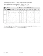
Flow Rate as per Valve Pressure Difference (

Δ

P) 

*For fully open valve position. 
For example:
The 

012+AL 

valve is with CV 0.30 (for sequence 1) and CV is 1.20 (for sequence 2). 

If  we  consider  the  valve  pressure  difference  (

Δ

P)  4  psid  then  as  per  above  table,  the  Flow  rate  for

sequence 1 will be 0.60 gpm and for sequence 2 will be 2.40 gpm. 

Valve 

Size

CV Value

Flow Rate (in gpm) for below Valve 

Δ

P (in psid)

(inch)

For Sequence 

1or 2*

0.50 0.75 1.00

2.00

3.00

4.00

5.00

6.00

7.00

8.00

9.00

10.00

1/2 inch

C

V

 0.30

0.21 0.26

0.30

0.42

0.52

0.60

0.67

0.73

0.79

0.85

0.90

0.95

C

V

 0.46

0.33 0.40

0.46

0.65

0.80

0.92

1.03

1.13

1.22

1.30

1.38

1.45

C

V

 0.80

0.57 0.69

0.80

1.13

1.39

1.60

1.79

1.96

2.12

2.26

2.40

2.53

C

V

1.20

0.85 1.04

1.20

1.70

2.08

2.40

2.68

2.94

3.17

3.39

3.60

3.79

C

V

 1.90

1.34 1.65

1.90

2.69

3.29

3.80

4.25

4.65

5.03

5.37

5.70

6.01

C

V

 3.00

2.12 2.60

3.00

4.24

5.20

6.00

6.71

7.35

7.94

8.49

9.00

9.49

C

V

 4.70

3.32 4.07

4.70

6.65

8.14

9.40

10.51

11.51

12.44

13.29

14.10

14.86

C

V

 7.40

5.23 6.41

7.40

10.47 12.82 14.80

16.55

18.13

19.58

20.93

22.20

23.40

3/4 inch

C

V

 4.70

3.32 4.07

4.70

6.65

8.14

9.40

10.51

11.51

12.44

13.29

14.10

14.86

C

V

 7.40

5.23 6.41

7.40

10.47 12.82 14.80

16.55

18.13

19.58

20.93

22.20

23.40

C

V

 10.00

7.07 8.66 10.00 14.14 17.32 20.00

22.36

24.49

26.46

28.28

30.00

31.62

C

V

 14.00

9.90 12.12 14.00 19.80 24.25 28.00

31.30

34.29

37.04

39.60

42.00

44.27

Table 3. Flow rate as per Valve Pressure difference

Summary of Contents for MN7510A2001

Page 1: ... use in chilled water and hot water closed loop applications only with a media temperature range of 0 ºF to 212 ºF 18 ºC to 100 ºC and static pressures up to 600 psi These valves are to be operated with the Honey well MN7510A2001 actuator only Water should be properly filtered treated and conditioned for good operating performance according to local conditions and recommenda tions of the boiler or...

Page 2: ...rd Foreign particles like dirt and metal chips can damage the ball seals For trouble free operation of the product good installation practice must include initial system flushing and chemical water treatment Clean the lines upstream of particles larger than 1 16 inch diameter welding slag pipe scale sand and other suspended particulate Use of a 50 micron or finer system side stream filter is sugge...

Page 3: ...valve to the supply and return pipes of the coil 6 Connect the A ports and B ports as per the flow sequences Refer to below figure Figure 1 Typical flow directions for Sequence 1 and 2 IMPORTANT Strictly follow flow direction and port connec tions as per flow sequences 7 Clear threads on both valve and piping of any debris Honeywell recommends Permabond A1044 or equivalent thread or pipe sealant W...

Page 4: ...g 1 Use a suitable plier to hold the clip of the Uni versal shaft adapter 2 Pull out the Clip as shown in below figure to remove Universal shaft adapter Now the actuator is ready to assemble on 6 way control ball valve Assembling the actuator on Valve body 1 Make sure that the Gear box is in zero posi tion as shown in below figure Use the appro priate wrench to adjust if necessary Figure 4 Zero po...

Page 5: ...to any position Rotate the Stem adapter so that the notch on the Stem adapter points as shown in figure below Figure 7 Adjusting the Stem adapter to zero position 5 Slide the Brass sleeve over the end of the Stem adapter as shown in figure below Figure 8 Assembly of Brass sleeve 6 Place the actuator assembly on the Valve body as shown in below figure Figure 9 Assembly on the Valve body IMPORTANT T...

Page 6: ...pressing it downwards press fit to assemble it firmly Figure 11 Mounting of Handle on the actuator Manual Adjustment IMPORTANT To prevent equipment damage you must remove power or set the function selection switch to the Service Off position before manual adjustment After removing power or setting the function selection switch to the Service Off position the Gear box can be disengaged using the De...

Page 7: ... use the appropriate electrical cable conduits and cable gland to properly secure the actuator wiring 4 Replace the wiring cover once done Actuator Run modes The function selection switch see Figure 16 can be used to place the actuator into any one of two different modes Modulating run mode Floating 2 position run mode Service Off mode Caution To avoid personal injury electrical shock and to preve...

Page 8: ... 13 then as soon as operating power is applied the shaft adapter will run first completely counterclockwise and then completely clockwise after which it will run according to the control signals applied Use the above flow curve with given actuator control signal settings to configure 6 way valve for Sequence 1 cooling Sequence 2 and Off position Note that in Figure 13 it is shown how to over ride ...

Page 9: ...hieve full clockwise full counterclockwise and precisely mid stroke actu ator positions If desired the actuator analog feedback can be used to verify actual position If only step 1 and 2 above are desired and there is no need for step 3 to rotate the actuator to exactly 45 degrees to turn both Sequence 1 and 2 completely off the floating mode may be used for 3 wire 2 position control Power Off Beh...

Page 10: ... 0 95 CV 0 46 0 33 0 40 0 46 0 65 0 80 0 92 1 03 1 13 1 22 1 30 1 38 1 45 CV 0 80 0 57 0 69 0 80 1 13 1 39 1 60 1 79 1 96 2 12 2 26 2 40 2 53 CV1 20 0 85 1 04 1 20 1 70 2 08 2 40 2 68 2 94 3 17 3 39 3 60 3 79 CV 1 90 1 34 1 65 1 90 2 69 3 29 3 80 4 25 4 65 5 03 5 37 5 70 6 01 CV 3 00 2 12 2 60 3 00 4 24 5 20 6 00 6 71 7 35 7 94 8 49 9 00 9 49 CV 4 70 3 32 4 07 4 70 6 65 8 14 9 40 10 51 11 51 12 44...

Page 11: ...NS Dimension of Valve body Table 2 Dimensions Valve nominal size A B C D E F Valve Body Inch inch mm inch mm inch mm inch mm inch mm inch mm VB6A 1 2 6 85 174 2 76 70 6 63 168 5 33 135 4 14 105 3 77 95 VB6B 3 4 7 01 178 3 07 78 6 92 176 5 46 139 4 15 105 4 09 104 Figure 18 Dimension of VB6 series 6 way control valve ...

Page 12: ...ll makes no representations or warranties with respect to this document In no event shall Honeywell be liable for technical or editorial omissions or mistakes in this document nor shall it be liable for any damages direct or incidental arising out of or related to the use of this document No part of this document may be reproduced in any form or by any means without prior written permission from H...

Reviews: