Honeywell MN7220 Product Data Download Page 8

Automation and Control Solutions

Honeywell International Inc.

Honeywell Limited-Honeywell Limitée

1985 Douglas Drive North

35 Dynamic Drive

Golden Valley, MN  55422

Scarborough, Ontario  M1V 4Z9

customer.honeywell.com

N20, N34 SERIES MN7220, MN7234

® U.S. Registered Trademark
© 2005 Honeywell International Inc.
63-2587—1    M.S.  Rev. 10-05 
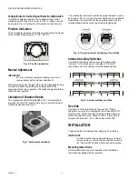
DIMENSIONS

60

30

0

90

shaft

adapter

shaft

adapter (reverse)

anti-rotation bracket

100 mm (3-15/16”)

20.6 mm
(1-3/16”)

48

 mm

(1

-7

/8

”)

95°

22

3 mm

 (

8

-2

5/

32”

)

92 mm (3-5/8”)

100

0 m

m

 (39”)

5 mm (+0.05, -0.10 mm)

25/128” (+0.002, -0.004”)

2 mm (5/64”)

20 mm (25/32”)

13 mm (1/2”)

7 mm (9/32”)

132 mm (5-3/16”)

min. 60 mm (2-3/8”)

230 mm [+/- 0.5 mm] (9-1/16” [+/-1/64”])

Summary of Contents for MN7220

Page 1: ...ltage 24 Vac 50 60 Hz 24 Vdc All values stated hereinafter apply to operation under nominal voltage conditions Power consumption MN7220 6 VA 6 W MN7234 8 VA 6 W Ambient limits Ambient operating limits 5 140 F 20 60 C Ambient storage limits 40 175 F 40 80 C Relative humidity 5 95 non condensing Safety Protection standard IP54 non USA models NEMA2 USA models Protection class II as per EN 60730 1 Ove...

Page 2: ...ct Identification System OPERATION FUNCTIONS Fig 2 Setting units and control elements Legend for Fig 2 Setting units and control elements 1 Self centering shaft adapter 2 Retainer clip 3 Rotational angle scales 0 90 90 0 4 Mechanical end limits 20 Nm 175 lb in models only 5 Declutch button 6 Anti rotation bracket 7 Rotation direction switch 8 Access cover 9 Internal auxiliary switch wire 10 Power ...

Page 3: ...hes view with PCB at bottom Autoadapt Dip Switch for Normal Operation In its default shipping position the autoadapt dip switch for normal operation is set to ON as shown in Fig 4 Dip switches view with PCB at bottom 4 If it is set to OFF no autoadapting is performed and the control signal map remains constant The autoadapt functionality does not have to be triggered Rather the SmartAct actuator d...

Page 4: ...8 Specifically it is important that they properly mesh with the rotational angle scales when the screws are tightened Fig 8 Correct incorrect tightening of end limits Internal Auxiliary Switches The internal auxiliary switches are set to change from common to normally open at angles of 5 and 85 respectively from the totally counterclockwise position Fig 9 Internal auxiliary switches Override If te...

Page 5: ...round In the case of short shafts the shaft adapter may be reversed and mounted on the duct side Stroke Limitation with Mechanical End Limits The mechanical end limits 20 Nm 175 lb in models only enable the stroke to be limited from 0 90 in increments of 3 Wiring Access cover To facilitate wiring the actuator to the controller the access cover can be detached from the actuator IMPORTANT Remove pow...

Page 6: ...ety isolating transformer connecting cable terminal name supply and signal lines 1 24 Vac 24 Vdc 2 24 Vac 24 Vdc 3Y 0 2 10 Vdc 0 4 20 mA control signal 5U 0 2 10 V feedback signal auxiliary switched when included CCW left 5 S1 Common S2 normally closed S3 normally open CW right 85 S4 Common S5 normally closed S6 normally open AUXILIARY S1 S2 S3 S4 S5 S6 S3 S2 S1 S6 S5 S4 AUXILIARY TERMINAL STRIP 2...

Page 7: ...N20 N34 SERIES MN7220 MN7234 7 63 2587 1 ...

Page 8: ...om N20 N34 SERIES MN7220 MN7234 U S Registered Trademark 2005 Honeywell International Inc 63 2587 1 M S Rev 10 05 DIMENSIONS 60 30 0 90 shaft adapter shaft adapter reverse anti rotation bracket 100 mm 3 15 16 20 6 mm 1 3 16 48 mm 1 7 8 95 223 mm 8 25 32 92 mm 3 5 8 1000 mm 39 5 mm 0 05 0 10 mm 25 128 0 002 0 004 2 mm 5 64 20 mm 25 32 13 mm 1 2 7 mm 9 32 132 mm 5 3 16 min 60 mm 2 3 8 230 mm 0 5 mm ...

Reviews: