


N20, N34 SERIES MN7220, MN7234
5
63-2587—1
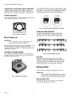
Mounting Position
The actuators can be mounted in any desired orientation (no
NEMA2 or IP54 if mounted upside down; see Fig. 10). Choose
an orientation permitting easy access to the actuator's cables
and controls.
Fig. 10. Mounting for IP54/NEMA2
Mounting Bracket and Screws
If the actuator is to be mounted directly on a damper shaft, use
the mounting bracket and screws included in the delivery
package.
Self-Centering Shaft Adapter
The self-centering shaft adapter can be used for shafts having
various diameters (3/8...1-1/16” [10...27 mm]) and shapes
(square or round).
In the case of short shafts, the shaft adapter may be reversed
and mounted on the duct side.
Stroke Limitation with Mechanical End Limits
The mechanical end limits (20 Nm [175 lb-in] models, only)
enable the stroke to be limited from 0...90° in increments of 3°.
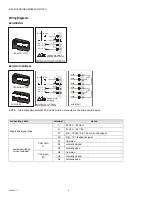
Wiring
Access cover
To facilitate wiring the actuator to the controller, the access
cover can be detached from the actuator.
IMPORTANT
Remove power before detaching the access cover.
Once the access cover has been removed, please
take care to avoid damaging any of the parts now
accessible.
Fig. 11. Access cover
Depending upon the model, the access cover may have one or
two terminal strips, including a layout with a description for
each of the terminals.
Fig. 12. Actuator with access cover removed
NEMA2
IP54
NEMA2
IP54
NEMA2
IP54
NEMA2
IP54