62-0400-01
INSTALLATION INSTRUCTIONS
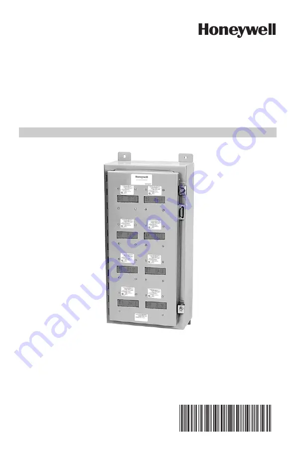
Honeywell Multiple Meter
Units (MMU)
KWH AND KWH/DEMAND
Page 1: ...62 0400 01 INSTALLATION INSTRUCTIONS Honeywell Multiple Meter Units MMU KWH AND KWH DEMAND ...
Page 2: ...MMU Cabinet Wiring 10 Section 6 1 MMU Cabinet Wiring 10 Section 6 2 MMU Cabinet Wiring 11 Section 6 3 MMU Cabinet Wiring 11 Section 7 0 Individual Meter Wiring Diagrams and Installation Procedures 12 Section 7 1 Class 100 200 and Green Class Meter Wiring Diagrams and Installation Procedures 12 Section 7 2 Class 320 Meter Wiring Diagrams and Installation Procedures 13 Section 7 3 IDR Interval Data ...
Page 3: ...with the meaning of each label to minimize risk The presence of this label is a cautionary indicator identifying a danger risk The manual should be consulted prior to proceeding The presence of this label indicates an electrical shock hazard exists in the location or area where the label is placed Prior to proceeding the MAINS power must be disconnected and the manual consulted for safety informat...
Page 4: ...ectrical shock exists Prior to performing any wiring operations review all contents of the user manual and de energize the MAINS power switch Only qualified personnel should perform installation wiring Installation wiring must comply with all local and national electrical codes CAUTION Failure to ground the enclosure creates a possible shock hazard Do not operate the MMU Style Meter without a prot...
Page 5: ... or institutional facilities Voltage and current are continuously measured and updated to provide highly accurate true RMS power information via current sensors 3 2 General Description The MMU allows for compact installation of multiple meters that allows for easy and centralized reading A single MMU cabinet can be configured to contain up to 8 16 or 24 meters of different voltage configurations i...
Page 6: ...ic power usage after the utility meter and store kW and kVAR data for automatic meter reading Refer to Sections 5 6 7 for general installation instructions on installing Class 320 meters into a MMU Cabinet 4 3 Green Class Meters The Green Class Meter is a power meter for use in sub metering applications The devices take inputs from current sensors and the line voltage and output kW hours in pulses...
Page 7: ...e four housing mounting holes are located on the upper and lower mounting brackets Serviceability field Repair Service and repair should be completed by qualified personnel only Meters cannot be calibrated in the field Adjustment is limited to reset of the meter display and should be performed by qualified personnel only The configuration is stated on each meter nameplate The MMU enclosure is not ...
Page 8: ...HONEYWELL MULTIPLE METER UNITS MMU 62 0400 01 8 Spaces not occupied by meters will have a blank metal cover over the display window Fig 3 Example of an 8 Meter MMU Enclosure ...
Page 9: ...as to be landed on the terminal block in order to power all of the meters in the MMU As with the stand alone meters the power wires must be fused The size of the fuse will be determined by the number of meters installed in the MMU The Littelfuse KLDR series are used for this component Each meter point requires 1 10 amp fusing With 8 meters a one amp fuse would be acceptable The current sensor wiri...
Page 10: ...edures will help to assure a satisfactory installation NOTE Units housed in UL type 1 enclosures must only be installed in indoor loca tions where they will not be affected by the elements 6 2 Grounding The meters and enclosure must be prop erly grounded for safety A protective earth ground lug is provided for this purpose Failure to ground the enclosure creates a possible shock hazard There are t...
Page 11: ... respective stand alone meter Refer to the stand alone Class 100 200 and Green Class Meter Installation Manuals for detailed wiring diagrams and installation procedures The menu buttons on the Class 100 MMU 200 MMU and Green Class MMU Meters are in the same positions as a stand alone Class 100 200 or Green Class Meters The MMU Menu Buttons are identified in the figure below Fig 6 Class 100 200 and...
Page 12: ...g diagrams and installation instructions NOTE The menu buttons on the Class 320 MMU Meter are reversed from the stand alone Class 320 Meters The menu buttons positions are identified in the fig ure below Fig 7 The Menu Buttons on a Class 320 MMU Meter are Reversed from the Stand Alone Version 7 3 IDR Interval Data Recorders Wiring Diagrams and Installation Procedures Refer to the IDR Installation ...
Page 13: ...ND RJ 45 6 COND RJ 45 IDR A IDR Z CONNECTION CABLE TYPE CONNECTOR IDR TO HONEYWELL METERS 1 8 6 COND 22 26 AWG RJ 45 PINS 1 8 NOT USED IDR TO IDR 4 COND 26 AWG RJ 11 IDR TO RS 232 KEY 2000 4 COND 26 AWG RJ 11 RS 232 KEY 2000 TO COMPUTER 8 COND 22 26 AWG RJ 45 DTE FLAT MODULAR CABLE RS 232 KEY 2000 TO MODEM 8 COND 22 26 AWG RJ 45 FLAT MODULAR CABLE IDR TO PULSE METER 2 COND 14 22 AWG SUPPLIED BY HO...
Page 14: ...D RJ 45 IDR A B IDR Y Z CONNECTION CABLE TYPE CONNECTOR IDR TO HONEYWELL METERS 16 6 COND 22 26 AWG RJ 45 PINS 1 8 NOT USED IDR TO IDR 4 COND 26 AWG RJ 11 IDR TO RS 232 KEY 2000 4 COND 26 AWG RJ 11 RS 232 KEY 2000 TO COMPUTER 8 COND 22 26 AWG RJ 45 DTE FLAT MODULAR CABLE RS 232 KEY 2000 TO MODEM 8 COND 22 26 AWG RJ 45 FLAT MODULAR CABLE IDR TO PULSE METER 2 COND 14 22 AWG SUPPLIED BY HONEYWELL NOT...
Page 15: ...O 16 METERS IDR 16 USING HONEYWELL METERS CHANNEL 2 CHANNEL 1 AC ADAPTER RS 485 to RS 232 Key SUB EKMT UP TO 16 METERS CHANNEL 3 RS 232 SERIAL PORT COM1 THROUGH COM4 MAX 15 LOCAL MODEM TELEPHONE LINK UP TO 52 IDRS PER CHANNEL UP TO 52 IDRS PER CHANNEL IDR A IDR Z IDR A IDR Z UP TO 8 METERS UP TO 8 METERS UP TO 8 METERS IDR 8 USING HONEYWELL METERS CHANNEL 2 CHANNEL 1 UP TO 4000 FEET TOTAL AC ADAPT...
Page 16: ... 2 CHANNEL 1 CHANNEL 3 UP TO 4000 FEET TOTAL UP TO 52 IDRS NOTES METERS 16 MUST BE INSTALLED WITHIN 500 FEET OF IDR METERS 16 USE 6 CONDUCTOR CAB AC ADAPTER RS 232 Key SUB RS232K RS 232 SERIAL PORT COM1 COM4 UP TO 8 METERS UP TO 8 METERS 15 FEET MAX IDR 8 USING HONEYWELL METERS IDR IDR IDR IDR PC UP TO 4000 FEET TOTAL UP TO 52 IDRS M33484 ...
Page 17: ...EET OF IDR METERS 16 USE 6 CONDUCTOR CABLE AC ADAPTER RS 232 Key SUB RS232K 6 FOOT CABLE PROVIDED BY HONEYWELL 15 FEET MAX RS 232 SERIAL PORT COM1 COM4 UP TO 16 METERS UP TO 16 METERS AC ADAPTER IDR IDR IDR IDR IDR IDR IDR IDR M33485 PC UP TO 4000 FEET TOTAL UP TO 4000 FEET TOTAL UP TO 26 IDR 16S PC 6 FOOT CABLE PROVIDED BY HONEYWELL 15 FEET MAX RS 232 SERIAL PORT COM1 COM4 RS 232 Key SUB RS232K U...
Page 18: ...these installation instructions your Honeywell meter should provide years of trouble free service If the meter should not function the following guide will assist in troubleshooting the installation Refer to the individual Meter Installation Manual for detailed troubleshooting information 9 0 METER TECHNICAL SPECIFICATIONS Refer to the individual Meter Installation Manual for detailed technical sp...
Page 19: ... work performed with Honeywell s authorization and according to its approved proce dures iii the alleged defect is a result of abuse misuse improper maintenance improper installation accident or the negligence of any party iv damaged as a result of events beyond Honeywell s control or other force majeure events or v used in conjunction with equipment components accessories parts or materi als not ...
Page 20: ...utomation and Control Solutions Honeywell International Inc 1985 Douglas Drive North Golden Valley MN 55422 customer honeywell com U S Registered Trademark 2012 Honeywell International Inc 62 0400 01 JPG Rev 10 12 Printed in United States ...