


VALUP
AK-II · Edition 11.22
EN-4
Please observe the following to ensure that no damage occurs:
– Before initiating the following start-up and adjustment proce-
dure, it is important that a check be made to verify that all of
the equipment associated with and necessary to the safe
operating of the VALUPAK-II burner system has been installed
and piped in accordance with the general installation instruc-
tions.
– If the burner system is part of an oven or other heating unit
which has been purchased as a complete prepiped and
pre-wired package, it may be assumed that these instructions
have already been carried out by the individual or company
responsible for the overall installation.
➔
Initial adjustment and light-off should be undertaken only by trained
and experienced personnel familiar with combustion systems,
with control/safety circuitry and with knowledge of the overall
installation.
7.1 to start-up a VALUPAK-II burner for the first time
1
Close main gas cock.
2
Check tightness of gas piping.
3
Connect U-tube manometer to burner test connection on the
burner gas nozzle inlet.
4
Note burner type and required gas pressure, see page 5 (10
Technical data).
5
Establish correct blower direction of rotation of all fans. See arrow
on blower housings.
6
Disconnect automatic control motor wiring to avoid unexpected
motor travel.
7
Check that gas control valve is at low fire position (as supplied):
For size 150, 300, 600 and 900 control motor rotation is counter
clockwise when looking towards controls linkage going from low
to high fire. For the size 60 when looking to the linkage the air
butterfly crank rotation is counterclockwise. Since the control
motor is located at the opposite side of the linkage its rotation is
clockwise from low to high fire.
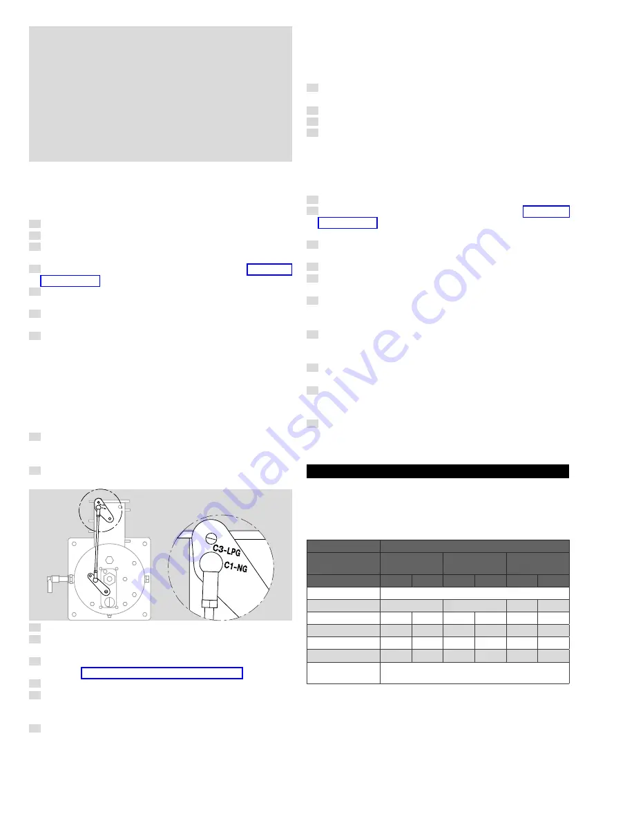
➔
When operating the burner with LPG instead of natural gas, the
linkage connection on the air valve crank needs to be changed.
8
In order to do this, unscrew the nut (M6) at the back of the crank
and relocate the linkage from the hole marked “C1–NG” to the
hole “C3–LPG” by slightly rotating the crank and linkage.
9
Screw the nut back in place. No further modification on the burn-
er needs to be done.
C
Detail C
C
Detail C
10
Bleed air from the fuel supply line.
11
Remove the cover from the gas pressure regulator and establish
that regulator is at low end of control range.
12
Check the adjustments of the flame rod, spark ignitor and/or
pilot, see page 3 (4.6.2 Spark ignitor arrangement).
13
Start all machine air blowers.
14
Start burner with its start-stop switch. Motor of combustion air
fan will be started shortly after, by means of the burner flame
safeguard programming relay.
15
Purge the combustion chamber, purging any explosive vapors
that may have accumulated prior to the start.
➔
The length of purge time required will usually be specified by
insurance or approval agency having jurisdiction and depends on
the total amount of fresh air and the volume of combustion space.
➔
A 5-fold refresh rate should be minimum. At the end of the purge
time of the burner flame safeguard programming relay ignition is
energized and the main gas valve will be energized shortly after.
➔
Because main gas cock is closed the programmer will lock out
requiring manual reset. Operation of programmer is correct.
16
Check setting of low and high gas pressure switches and com-
bustion air pressure switch.
17
Check burner control valve at LO position.
18
Slowly open main gas cock.
19
Reset burner relay and start burner.
➔
After the burner flame safeguard programmer relay prepurge time
ignition is energized and main gas valve opened. Flame should
be established within safety time of programmer.
➔
If again flame failure, air could still be in gas supply line just before
burner.
20
Reset programmer and restart until low fire flame is established.
21
Check gas supply pressure with information on page 5 (10
Technical data) and correct with adjusting screw of gas pressure
regulator.
22
In the case of LPG firing, multiply the referenced natural gas
pressures by 0.4 to arrive at optimal LPG pressures.
23
Observe flame through observation port at rear of burner.
24
Slowly bring burner to high fire position and avoid maximum
temperature of dryer.
25
Close cover on pressure regulator and adjust all pressure switch-
es. High gas pressure switch at low fire. Low gas pressure switch
at high fire.
26
Close cover on pressure regulator and adjust all pressure switch-
es. High gas pressure switch at low fire. Low gas pressure switch
at high fire.
27
Air pressure switch at high fire by closing of air inlet until flame
color start to change. Burner should trip by air pressure switch.
28
Reconnect control motor wiring, start burner and change sever-
al times between low and high fire position by changing temper-
ature controller settings.
29
Check all other safety devices such as pressure switches, high
temperature limits etc. and adjust these devices to their correct
values.
8 VALUPAK PACKAGe AnD BACK PRessURe
8.1 stable back pressure
Burner capacity will depend on back-pressure.
VP-II-150–900: The standard package can be used with stable back
pressure between -2.0 and +2.0 mbar except for VP-II-60.
VP-II-60: See the table below.
Back-pressure
Capacities kW (HHV)
VP-II-60
UHC102
VP-II-60
UHC122
VP-II-60
UMI300
min.
max.
min.
max.
min.
max.
< 2 mbar
not possible
2 mbar
not possible
not possible
3
65
1 mbar
2
25
2
50
3
75
0 mbar
2
40
2
60
3
80
- 1 mbar
3
45
3
65
4
90
- 2 mbar
3
50
4
70
5
100
< - 2 mbar
Not advised, please contact HTS sales or
customer contact.
Once set for a specific back pressure:
– The package can fire stable on lower back pressures, but (min
and max) capacity will increase, excess air will increase and
higher CO/C
x
H
y
could be the result.
– The package cannot be used on higher back pressures: this
would result in reduced air factor, possible below 1.0 (with
longer flames, incomplete combustion etc.).


