LTE-X Series Installation and Setup Guide
– 3 –
Compliance
This device has been tested by ETL to meet the following standards:
•
UL985 – Residential Fire
•
Canadian ULC Compliance
•
UL1023 – Residential Burg
Mount and Wire the Module
Select a Mounting Location
When choosing a suitable mounting location, understand that it must be mounted indoors, and for best signal strength it
should be mounted vertically. Signal strength is very important for proper operation. For most installations, mounting
the unit on the control panel provides adequate signal strength and we suggest that this method is tried first. Especially
if the control panel is not in a basement location or in an area that contains large metal objects.
If the control panel location does not provide adequate signal strength, then the communicator can be mounted remotely.
Verify Satisfactory Signal Strength
This procedure checks for satisfactory signal strength at the communicator. You can temporarily power the communicator
from a 12V battery or from the control panel's AUX PWR terminals. In buildings where reception may be a problem,
powering from a battery would allow the communicator to be portable. The following procedure assumes the control panel
will be used for power. (If satisfactory signal strength is present at the control panel that is the preferred mounting
location.)
1.
Ensure power to the control panel (both AC and battery) is off. Open the enclosure and connect the ECP cable
connector to the communicator. Connect the cable wires to the control’s ECP terminals.
2.
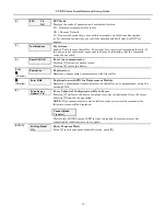
Turn power on and wait for the communicator to initialize*. Position the communicator near a suitable mounting
position. Verify the SIGNAL LED (green) lights steady. This indicates satisfactory signal strength.
*
LTE-XV Initial Power Up
: Upon initial power up, the
communicator LEDs blink in repeated sequence from top to
bottom indicating network initialization.
Green (REG)
Yellow (TX/RX)
Red (FAULT)
Green (SIGNAL)
This sequence may take up to 15 minutes.
Do not reset
power during this time.
During the final stages of initialization, the Green REG LED
lights solid while the Red FAULT LED lights solid on or
flashes rapidly (if module not connected to the control panel
ECP).
When initialization is complete, the Green signal strength
LED lights solid (the yellow and red LEDs may also blink, per
their respective functions).
After initial network setup, subsequent resets or power ups
can take up to 90 seconds.
3.
Verify the SIGNAL LED (green) remains steady for a few minutes, then mark that mounting position. Turn
power off.


