background image

4

LP916A-C PNEUMATIC REMOTE BULB THERMOSTATS

95-5559

E

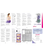
Place capillary tubing in bulb holder channel and pinch
top edges of holder together at each segment as shown
in Figure 9.

Fig. 9. Mounting capillary tubing in bulb holder.
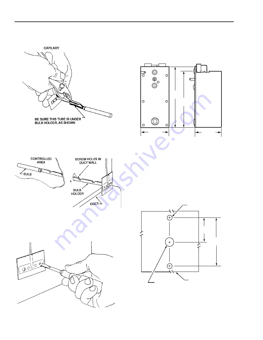
F

Insert bulb and bulb holder (Fig. 10) into duct through
hole prepared in Step 1.

Fig. 10. Inserting bulb and bulb holder into duct.

G

Fasten bulb holder to duct wall with screws as shown in
Figure 11.

Fig. 11. Fastening bulb holder to duct wall.

Mounting Kit Model

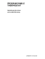
The LP916 mounting kit model is shown in Figure 12. This
model can be either panel mounted or mounted in a terminal
unit using a bracket.

Fig. 12. LP916 mounting kit model

dimensions in inches (millimeters).

Panel Mounting

Mounting LP916 Mounting Kit Model directly on a panel
requires a 306016C Bag Assembly which includes a scale
plate, knob, and mounting screws.

A

Drill holes in panel on centers as shown in Figure 13.

Fig. 13. Hole dimensions in inches (millimeters) for panel

mounting LP916 mounting kit model.

C4650

3/8 (10) DIA

7/32 (6) DIA -2

PANEL

2-1/4

(57)

1-1/8

(29)

S24103

S24105

S24104

C4653

4-1/2
(115)

4-7/8
(124)

2-3/16 (56)

2-1/16 (53)

C4653

B

M

+

+

+

+

+

+

+

Summary of Contents for LP916A-C

Page 1: ...an two revolutions clockwise from the original position as received Rotating the shaft more than two revolutions from the original position can cause permanent damage to the Thermostat This warning is also on a removeable tag Fig 1 attached to the Thermostat and should remain attached until the system is ready to start up Fig 1 LP916 caution label O O L E R W A R M E M B H O N E Y W E L L CAUTION ...

Page 2: ... 14 4 5 8 117 2 3 4 70 3 77 Fig 3 Typical terminal unit mounting locations B Mount Thermostat in location where mounting screws are readily accessible setpoint knob easily reached and scale visible preferably from top of unit through access hatch or from front of unit when front panel is removed C Locate air connections in accessible area If necessary add 1 4 in plastic elbow and or tubing extensi...

Page 3: ...dry tubing Air connections are 1 4 in push on sharp barb type and are labeled M and B for Main and Branch NOTE If air connections are towards back connect appropriate lengths of tubing to barb connectors before mounting Duct Mounting Duct mounting requires a 107324A Duct Bulb Holder Fig 7 The sensing bulb should be located in the duct where air of representative temperature can freely circulate ar...

Page 4: ... wall Mounting Kit Model The LP916 mounting kit model is shown in Figure 12 This model can be either panel mounted or mounted in a terminal unit using a bracket Fig 12 LP916 mounting kit model dimensions in inches millimeters Panel Mounting Mounting LP916 Mounting Kit Model directly on a panel requires a 306016C Bag Assembly which includes a scale plate knob and mounting screws A Drill holes in pa...

Page 5: ...red Bracket Mounting The LP916 Mounting Kit Model is installed in terminal units similar to Figure 5 or 6 using a 306016A or B Bag Assembly These assemblies include a mounting bracket screws nuts clips bulb hangers scale plate and knob The two bag assemblies are similar except for the length of the mounting bracket and the centers of the bracket mounting holes Fig 15 and 16 The two sets of holes i...

Page 6: ...alibration C Hold Thermostat in place in the terminal unit and mark screw hole centers Fig 17 Punch or drill pilot holes in the mounting surface for sheet metal screws Alternately Tinnerman nuts can be used by making clearance holes for the screws D Mount Thermostat in unit E Mount sensing bulb in unit using hangers see Fig 6 Fig 17 Assembling thermostat mounting bracket and scale plate bracket fr...

Page 7: ...B Measure temperature at bulb location C Remove setpoint knob D Rotate control shaft to achieve 8 psi 55 kPa branchline pressure Do not rotate shaft more than two revolutions clockwise from original position as received and allow enough time up to three minutes for branch pressure to build up WARNING Rotating shaft more than two revolutions clockwise from original position can cause permanent dama...

Page 8: ...aft clockwise Allow enough time up to three minutes for branch pressure to build up C Lower main line pressure to 16 5 psi 113 kPa Tighten switchover spring adjusting nut until branchline pressure begins to increase Allow enough time up to three minutes for branch pressure to build up and observe WARNING in LP916A and C calibration D Except LP916B1058 lower main line pressure to 13 psi 90 kPa Adju...

Reviews: