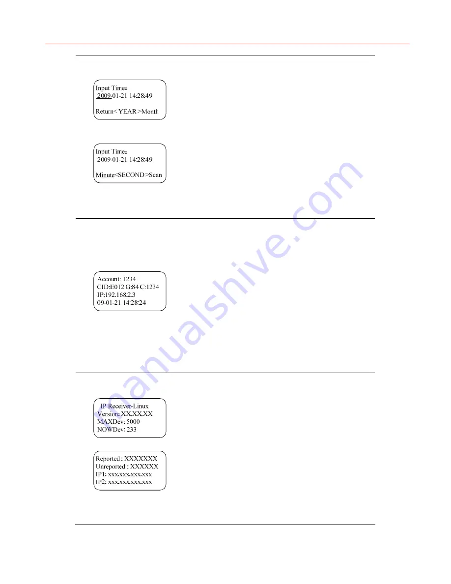
background image

Honeywell 


Figure 6 


Figure 7


Search by time


In 

Figure 5

, select “Search by Time” and 

Figure 6

 is 

displayed. 
It displays the current date and time. Press 

 and 

 to switch to the time item to be modified and 

press 

 and 

 to adjust the number of date and 

time. 
When “YEAR” is selected, press 

 to go to the 

previous menu. 
When “SECOND” is selected, press 

 to start 

searching alarm by time. The result displays the 
previous alarm occurred before the specified time. If 
no alarm occurred before the specified time, it 
displays the next alarm occurred after the specified 
time. 


Figure 8 

Display alarm


The searching result includes: 

  Account (a 4-digit account or the last four digits 

of a 6-digit account) 

  CID (Contact ID), G (Group ID), and Zone 

number (C)/User number(U)(depending on the 
reported alarm),  

  IP – the IP address of the device which reports 

the alarm (if unavailable, display “0.0.0.0”) 

  Date and time when reporting the alarm 

Press 

 or 

 to view the previous alarm; 

Press 

 or 

 to view the next alarm; 

Press 

ENTER

 to return to the alarm-selection menu 

shown in 

Figure 5

.  


Figure 9


Figure 10


View system information 

In 

Figure 3

, select “System Info” and the left figure 

is displayed. It includes the device name (Model), 
software version (Version), maximum number of 
devices (MAXDev) that can be connected 
(depending on dongle), number of the currently 
connected devices (NOWDev), number of reported 
alarms (Reported), number of unreported alarms 
(Unreported) and two IP addresses (IP1 and IP2) of 
the two network ports on IP Receiver for connecting 
IP devices. 
Press 

 and 

 to turn the page up and down; 

Press 

 or 

ENTER

 to return to the menu shown 

in 

Figure 3

.  

25 

Summary of Contents for IP Receiver

Page 1: ...Honeywell 网络接警机 IP Receiver 说明书 User Guide 2009 Honeywell International Inc All rights reserved http www cn security honeywell com P N 800 01188 Rev A ...

Page 2: ......

Page 3: ...Honeywell i 目录 1 产品介绍 1 2 产品示意图 3 前面板 3 后面板 4 3 系统配置 5 4 功能操作 6 5 网络操作 9 网络操作初始化 9 登录 10 配置 11 查询 12 导出记录 13 修改密码 13 退出系统 14 6 接警平台网络结构及路由器配置 15 ...

Page 4: ...ront Panel 21 Rear Panel 22 3 System Configuration 23 4 Operations 24 5 Network Operations 27 Initialization 27 Login 28 Configuration 29 Search 30 Export Result Records 31 Changing Password 31 Logout 32 6 Network Structure of IP Receiver and Configuration on Router 33 ...

Page 5: ...接收到的警情上报到 CMS 接警中心 并保存在自身数据库中 用户可以通过前面板按 键 显示屏查询报警信息 以及登录 网络接警机系统 查询 管理 备份收到的警情 网络接警机具有以下功能 最多连接 10000 个报警设备 由软件狗决定 自身最多能存储 10 000 000 条报警消息 提供 网络接警机系统 供用户远程登录进行数据库和配置操作 显示屏和操作按键 可用于查询 系统操作状态 LED 显示 通过 RS232 串口线连接 CMS 接警中心 每天凌晨 00 00 如果数据库中保存的数据大于 1 000 000 条 则会删除最老的 1 000 000 条报警信息 网络接警机的应用示意图如下 图 1 1 应用示意图 1 ...

Page 6: ...Honeywell 产品规格 输入电压 180 265V AC 尺寸 177mm H 482 6mm W 452mm D 重量 15 20 kg 显示屏 4 行 20 字符真空荧光显示 VFD 安装方式 机架式安装 工作温度 0 50 装箱清单 名称 数量 网络接警机 1 台 说明书 1 本 串口线 1 条 2 ...

Page 7: ... 编号 名称 1 VFD 显示屏 5 系统状态灯 2 排风口 6 报告状态灯 3 网络指示灯 7 ENTER MENU 确认 菜单键 4 通讯指示灯 8 四向导航键 LED 指示灯状态说明见下表 指示灯 说明 ETHERNET 当有 IP 设备连接到网络接警机时 绿灯亮 无任何设备连 接时 绿灯灭 COMM 当网络接警机与 CMS 接警中心串口连接时 绿灯亮 未连 接时 红灯亮 EVENT 上报警情时 绿灯闪烁 SYSTEM 当系统处于非正常工作状态 前面板与主板的串口线未连 接 红灯亮 正常运行时 绿灯亮 3 ...

Page 8: ...板 后面板接口示意图如下所示 图 2 2 网络接警机后面板示意图 编号 名称 编号 名称 1 三芯交流电源接口 220V 输入 7 千兆网口 1 2 COM2 8 千兆网口 2 3 COM4 9 VGA 4 COM3 10 硬盘状态灯 5 USB2 0 11 系统电源灯 6 PS 2 接口 12 主机开关 CMS 接警中心可以通过交叉串口线连接至网络接警机上的 COM2 端口 通信端口 COM2 为 9 针 COM 端口 4 ...

Page 9: ...示 图 3 1 Internet Protocol TCP IP 属性窗口 在上图所示的窗口中 选择 使用下面的 IP 地址 并在 IP 地址 中设置一个与 默认 IP 地址处于同一子网的 IP 地址 例如 192 168 0 3 或 192 168 1 3 点击 确定 按钮完成配置 2 将 PC 机与网络接警机的千兆网口相连 如第一步中配置的 IP 地址为 192 168 0 X 则 PC 机应与千兆网口 1 相 连 如配置的 IP 地址为 192 168 1 X 则 PC 机应与千兆网口 2 相连 注意 3 登陆 网络接警机系统 修改网络地址配置 如与千兆网口 1 相连 则在IE中输入 http 192 168 0 2登录该系统 如与千兆网口 2 相连 则在IE中输入 http 192 168 1 2登录该系统 详细配置步骤请见第9页网络操作初始化一节 5 ...

Page 10: ... 按 键 返回待机界面 见图 2 图 4 查询报警事件 在图 3 中选择 Search Alarm 显示左图菜单 共有三种查看方式 全部警情 All Alarms 已上报警情 Reported Alarm 未上报警情 Unreported Alarm 未上报警情 Unreported Alarm 如果网络接警机未能和 CMS 接警中心连接 那么收到的警情全部储存在数据库中 保存为未上报警情 按 或 ENTER 键选择菜单项 按 键或选择 Return 返回 上级菜单 图 5 选择需要查看的警情 在图 4 中选择需要查看的方式 显示左图菜单 共都有三种查看方式 最后一条警情 Last Alarm 第一条 警情 First Alarm 按照时间来查看 Search by Time 按 或 ENTER 键选择 按 键或选择 Return 返回上级菜 单 6 ...

Page 11: ... ID 防区号 C 用 户号 U 根据上报警情而定 IP 上报警情的设备 IP 地址 如无法获取到 IP 信息 则显示 0 0 0 0 警情上报时间 按 或 键查看当前警情的前一条警情 按 或 键查看当前 警情的后一条警情 按 ENTER 键返回警情选择菜单 见图 5 图 9 图 10 系统信息 在图 3 中选择 System Info 显示当前设备的名称 Model 软件的版本号 Version 能够连接的最大设 备数 MAXDev 根据软件狗而定 已经连接的设备数 NOWDev 已经上报的警情数 Reported 未上报的 警情数 Unreported 和网络接警机连接 IP 设备的两个网口 的 IP 地址 IP1 IP2 按 和 键翻看信息 按 或 ENTER 键返回选择菜单 见图 3 图 11 当前面板和主板的串口线连接不正常并持续一段时间后 1 分 钟以内 显示 Scanning...

Page 12: ...Honeywell 注意 无任何按键操作 30 秒后 屏幕自动返回待机画面 见图 2 每天凌晨 0 0 0 时 系统会对前面板屏幕进行检测 屏幕状态依次 全亮 2 秒 全灭 2 秒 回到正常待机状态 8 ...

Page 13: ...置网络接警机的IP地址 1 在IE中输入http 192 168 0 2或http 192 168 1 2进入网络接警机系统登录页面 登 录页面见图 5 2 2 登录网络接警机系统 详细内容参见第10页登录一节 3 在 配置 页面下 在 网络地址 1 中为千兆网口 1 设置一个未被其他设备占用 的 IP 地址 在 网络地址 2 中为千兆网口 2 设置未被其他设备占用的 IP 地址 点 击 执行 保存配置内容 下图为网络接警机的配置页面 参见第11页配置一节获取更多信息 图 5 1 网络接警机 IP 初始配置 网络地址 1 对应于千兆网口 1 的 IP 地址 网络地址 2 对应于千兆网口 2 的 IP 地址 配置时两者不可颠倒 注意 9 ...

Page 14: ...er IE 中输入接警机的 IP地址 需查看具体IP地址 请参见第6页第4章节中的图 10 登录网络接警机系统 如果PC机属于外网 网络接警机属于路由器内网时 需先按第6章节 第15页 对路由器进行配置 再在IE中输入路由器WAN端的IP地址 登录网络接警机系统 注意 图 5 2 网络接警机系统登录 输入用户名和密码 默认用户名和密码 admin admin 点击 登录 进入系统 图 5 4 或点击 重置 清空用户名和密码 如果用户名或密码错误 则显示以下提示信息 图 5 3 用户名密码错误 10 ...

Page 15: ...Honeywell 点击 返回重新登录 返回到登录页面 图 5 2 配置 成功登录系统后 显示如下页面 系统包括三个功能标签页 配置 查询 和 报告 在页面右上角可以选择 修改密码 和 退出 其下方显示当前的版本号 图 5 4 配置 网络配置 页面显示两个网卡的相应的网址 子网掩码和网关地址 可直接在输入框 中修改参数 修改完成后点击 执行 保存新配置 显示下图提示 图 5 5 配置成功 11 ...

Page 16: ...址不完整或出现大于 255 的情况 系统将显示错误提示信 息 注意 查询 点击 查询 标签页 进入查询页面 图 5 6 查询 页面左侧列出六种查询方式 按帐号查询 按时间查询 按网址查询 按 CID 查询 组 合查询和高级查询 其中 高级查询 支持输入 sql 查询语句 组合查询 把各个组合的 查询综合到一起显示在查询结果中 在页面左侧点击任一查询方式显示各查询页面 输入相应信息 点击 执行 以报告 的形式显示查询结果 12 ...

Page 17: ...查询结果 每页显示 20 条数据 通过点击页数编号或者 下一页 最后一页 可以查看相应页 面 导出记录 在查询结果页面 如图 5 7所示 的左下角点击 导出 按钮 可以将查询结果记录中的 最近 5000 条记录导出到Excel文件中 如查询结果记录总数小于 5000 条 则按时间由近至远 的顺序导出所有记录 如查询结果记录总数大于 5000 条 则导出最近 5000 条记录 修改密码 在页面右上角点击 修改密码 显示如下页面 13 ...

Page 18: ...Honeywell 图 5 8 修改密码 输入当前密码 并输入新密码并再次确认 点击 确认 完成修改密码操作 提示修 改密码成功 图 5 9 修改密码成功 注意 当前密码输入错误或者两次新密码输入不一致时 将显示错误提示 退出系统 在页面右上角点击 退出 则退出系统并返回到登录页面 14 ...

Page 19: ...对路由器进行一定配置以保证网络接警机安全 有效接警 以下配置以 Tenda TEI6624 路 由器为例 1 在IE中输入http 192 168 0 1 打开路由器配置界面 2 关闭 DHCP 功能 DHCP 自动分配 IP 地址 可能造成网络接警机 IP 地址不固定 从而无法接警 DHCP 配置页面如下图所示 图 6 1 DHCP 配置 3 设置虚拟服务器以便接受广域网报警 需要设置的端口有 TCP 7838 TCP 4001 TCP 4002 启用这些端口以便网络接警机能有效的收到广域网的报警 虚拟服务器配置页面如下图所示 15 ...

Page 20: ...Honeywell 图 6 2 虚拟服务器配置 4 安全设置 安全设置对网络接警非常重要 忽略来自 WAN 口的 Ping 包 避免恶意侦测 启用防网络攻击 防止 DOS 攻击 启用过滤功能 仅允许通过 TCP 7838 TCP 4001 TCP 4002 端口的数据 包 防止恶意入侵 加强路由器密码管理 避免密码被破解 忽略来自 WAN 口的 Ping 包 图 6 3 WAN 口 Ping 16 ...

Page 21: ...Honeywell 启用防网络攻击 图 6 4 防网络攻击 过滤端口配置 图 6 5 客户端过滤 最后 将路由器密码设置为安全性较高的密码 位数不少于 15 由字母 数字 特殊 符号组成 经过以上配置后 网络安全性将大大增加 有助于网络安全接警 17 ...

Page 22: ...使用手册 2 产品中有毒有害物质或元素的名称及含量见下表 产品中有毒有害物质或元素的名称及含量 有毒有害物质或元素 部件名称 铅 Pb 汞 Hg 镉 Cd 六价铬 Cr VI 多溴联苯 PBB 多溴二苯醚 PBDE 箱体组件 X O O O O O 印刷电路板组件 X O X O O O 线缆 X O O O O O 电源模块 X O O O O O LED 显示器 X O O O O O O 表示该有毒有害物质在该部件所有均质材料中的含量均在 SJ T11363 2006 标准规 定的限量要求以下 X 表示该有毒有害物质至少在该部件的某一均质材料中的含量超出 SJ T11363 2006 标准规定的限量要求 18 ...

Page 23: ...nel and log in the IP Receiver System to search manage and back up the received alarms Features Up to 10000 alarm devices can be connected to IP Receiver as determined by Dongle Up to 10 000 000 alarm records can be stored in the database An IP Receiver System for remote database operations Screen display and operating buttons for searching operation LED indicators for system operations A RS232 se...

Page 24: ... AC Voltage Input Dimension 177mm H 482 6mm W 452mm D Weight 15 20 kg Display 4 lines 20 characters VFD Mounting Rack Mounting 0 50 Operating Temperature Package checklist Name Quantity IP Receiver 1 User Guide 1 Serial port cable 1 20 ...

Page 25: ...THERNET The indicator turns green when the IP device is connected to IP Receiver and turns off when no device is connected to IP Receiver COMM The indicator turns green when IP Receiver is connected to the serial port of CMS and turns red when IP Receiver is not connected to CMS EVENT The indicator is green and flashes when IP Receiver is reporting alarms SYSTEM The indicator turns red when the sy...

Page 26: ...core AC Power Interface 220V Input 1 7 Gigabit Ethernet port 1 2 COM2 8 Gigabit Ethernet port 2 3 COM4 9 VGA 4 COM3 10 HDD Indicator 5 USB2 0 11 Power Indicator 6 PS 2 12 Power ON OFF switch CMS can be connected to the COM2 port on IP Receiver with a crossover serial port cable The communication port COM2 is a 9 pin COM port 22 ...

Page 27: ...window shown above select Use the following IP address In the IP address field specify an IP address for example 192 168 0 3 or 192 168 1 3 that belongs to the same subnet of the factory default IP address Click OK to save the application 2 Connect PC to the gigabit Ethernet port of IP Receiver Note If the IP address set in step 1 is 192 168 0 X connect your PC to gigabit Ethernet port 1 if the IP...

Page 28: ...Press to return to idle mode display Search alarm In Figure 3 select Search Alarm and the left figure is displayed There are three options for searching alarms All Alarms Reported Alarm and Unreported Alarm Unreported Alarm If IP Receiver is not connected with CMS all the alarms are stored in the database of IP Receiver as unreported alarms Press or ENTER to select the menu item Press or select Re...

Page 29: ...up ID and Zone number C User number U depending on the reported alarm IP the IP address of the device which reports the alarm if unavailable display 0 0 0 0 Date and time when reporting the alarm Press or to view the previous alarm Press or to view the next alarm Press ENTER to return to the alarm selection menu shown in Figure 5 Figure 9 Figure 10 View system information In Figure 3 select System...

Page 30: ... rear panel No 12 in Figure 2 2 It costs about 15 seconds to end the programs before displaying Shutting down If there is no key entry within 30 seconds the screen automatically returns to the idle mode display see Figure 2 Note The system checks the front panel screen at 0 0 0 every midnight the screen turns on for 2 seconds turns off for 2 seconds and then returns to the idle mode mode 26 ...

Page 31: ...ge 28 for the login page 2 Log in IP Receiver System For more information see Login on page 28 3 On the Configuration page specify an unoccupied IP address in the field of IP_address1 for gigabit Ethernet port 1 and specify a second unoccupied address in the field of IP_address2 for gigabit Ethernet port 2 Click Run to save the configuration The following figure shows the configuration page of IP ...

Page 32: ... Configuration on Router on page 33 and then input the IP address of the router s WAN port in IE to log in IP Receiver Figure 5 2 IP Receiver Login Input the username and password the default username and password is admin admin and click Log in to enter the system see Figure 5 4 on page 29 or Clear to clear the username and password If the username or password you entered is incorrect the followi...

Page 33: ... Log out below which is the current version Figure 5 4 Configuration The Network configuration page shows the corresponding IP address subnet mask and gateway of the two network adapters Change the parameters in the textboxes and click Run to save them as shown in the following figure Figure 5 5 Configuration Successful Note If the IP address is incomplete or has a value greater than 255 the syste...

Page 34: ...ed search Among them Advanced search supports the SQL query sentences and Combination search can integrate all the search combinations and display the search results in the result page Click one search way in the left pane and the corresponding search page is displayed Input the parameter and click Search and the search results are displayed in the report Figure 5 7 The Search Result Page 30 ...

Page 35: ...ed to the XLS file in which the records are arranged in reverse chronological order If the result records are more than 5000 the system only exports the latest 5000 records Changing Password Click Change Password on the top right corner of the page and the following page is displayed Figure 5 8 Changing Password Input the current password the new password and confirm it Click OK to change the pass...

Page 36: ... is displayed if the current password entered is incorrect or the new password and confirm password do not match Note Logout Click Log out on the top right corner of the page can log out the system and return to the login page 32 ...

Page 37: ...tion page of the router by entering the IP address http 192 168 0 1 in IE 2 Disable DHCP server DHCP server assigns IP address automatically which might cause IP Receiver to be assigned dynamic IP address and fails to receive the alarms The configuration page of DHCP is displayed as follows Figure 6 1 DHCP Setting 3 Set the virtual server to receive the alarms from WAN The ports to be set include ...

Page 38: ... Ping packets from the WAN port to avoid malicious detection Enable the function of anti network attack to prevent DOS attack Enable the filter function to allow the data packets of TCP 7838 TCP 4001 and TCP 4002 to pass through only which prevents malicious intrusion Strengthen the router s password management to avoid password cracking 34 ...

Page 39: ...n for filters Figure 6 4 Client IP Filters Lastly set a strong password for the router minimum of 15 characters in length composed of letters numbers and special characters After the preceding configuration the network security can be improved a lot and secure alarm receiving is strengthened 35 ...

Page 40: ...ell Security Asia Pacific 35F Tower A City Center 100 Zun Yi Road Shanghai 200051 China TEL 86 21 52574568 FAX 86 21 62370740 Honeywell Security China Co Ltd Building 9 Tower B Huaide Industrial Zone Fuyong Town Baoan District Shenzhen China TEL 86 0755 27326500 FAX 86 0755 27391736 2009 Honeywell International Inc http www cn security honeywell com http www security honeywell com ...

Reviews: