H8908A/B HUMIDISTAT H8908C/D DEHUMIDISTAT
69-1341EF—01
4
WIRING
CAUTION
Personal Injury Hazard.
Can cause electrical shock and injury.
Disconnect power before installation or servicing.
All wiring must comply with applicable local codes,
ordinances and regulations. Make wiring connections
according to humidifier (or dehumidifier/ventilator)
instructions, if available; otherwise, see typical wiring
diagrams in Fig. 12–19.
IMPORTANT
Select models of fan centers include humidifier
taps so the current sensing relay or sail switch is
not needed. If not using a current sensing relay
or sail switch, the humidifier must be energized
during blower motor cycles for proper operation.
On multispeed blower applications, do not wire
the high voltage side of the transformer to the
same power source that services the furnace
blower. Premature transformer burnout can
occur. On HE365 fan powered humidifier mod-
els, only the two yellow wires are connected to
the control. The remaining two red wires are only
used with electronic humidity controls.
6.
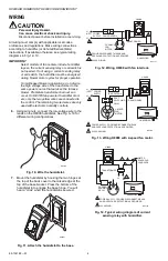
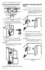
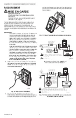
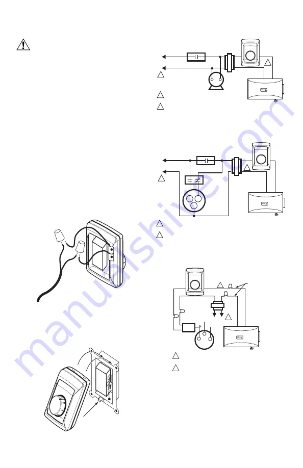
Using wire nuts, connect the low-voltage wire to the
leads on the H8908 humidistat. See Fig. 6–19 for
different wiring configurations.
Fig. 10. Wire the humidistat.
7.
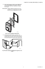
Mount the humidistat by hooking the two hinges at
the top of the back cover to the raised edge at the
top of the base bracket. Press the bottom of the
humidistat in to engage the base hinge. You will
hear a “click” when the humidistat is secured.
Fig. 11. Attach the humidistat to the base.
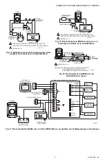
Fig. 12. Wiring H8908 with fan interlock.
Fig. 13. Wiring H8908 with 2-speed fan motor.
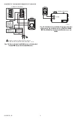
Fig. 14. Typical wiring diagram of current
sensing relay with humidifier.
M24734
M24801
H8908
1
1
2
PROVIDE DISCONNECT MEANS AND
OVERLOAD PROTECTION AS REQUIRED.
24 VAC WIRING.
2
HUMIDIFIER
TRANSFORMER
FURNACE
FAN
MOTOR
FAN CONTROL
L1
(HOT)
L2
M24727
POWER
SUPPLY
10
OFF
ON
20
30
40
50
60
1
1
H
L
C
2
POWER
S
UPPLY. PROVIDE DI
S
CONNECT MEAN
S
AND OVERLOAD PROTECTION A
S
REQUIRED.
24 VAC WIRING.
2
HUMIDIFIER
TRAN
S
FORMER
2-
S
PEED
FAN
MOTOR
DP
S
T
S
WITCHING
RELAY
FAN CONTROL
L1
(HOT)
L2
M2472
8
POWER
S
UPPLY
H
8
90
8
10
OFF
ON
20
30
40
50
60
M24729
L1
(HOT)
L2
1
2
1
2
POWER
S
UPPLY. PROVIDE DI
S
CONNECT MEAN
S
AND OVERLOAD PROTECTION A
S
REQUIRED.
24V WIRING.
HUMIDIFIER
TRAN
S
FORMER
WATER
S
OLENOID
LEAD WIRE
CURRENT
S
EN
S
ING
RELAY
C
LO
HI
H
8
90
8
10
OFF
ON
20
30
40
50
60

