Fire-Lite
®
and LiteSpeed
®
are registered trademarks of Honeywell International, Inc. Testifire
®
is a registrered trademark of SDi, LLC.
offer maximum performance when tested and maintained in compliance with
NFPA 72.
The sensor can be tested in the following ways:
A. Functional: Magnet Test (P/N M02-04-01 or M02-09-00)
This sensor can be functionally tested with a test magnet. The test magnet
electronically simulates smoke in the sensing chamber, testing the sensor
electronics and connections to the control panel.
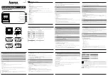
1. Hold the test magnet in the magnet test area as shown in Figure 3.
2. The sensor should alarm the panel.
Two LEDs on the sensor are controlled by the panel to indicate sensor
status. Coded signals, transmitted from the panel, can cause the LEDs to
blink, latch on, or latch off. Refer to the control panel technical documen-
tation for sensor LED status operation and expected delay to alarm.
B. Smoke Entry
Sensitivity readings are available through the FACP. Refer to the manufac-
turer’s published instructions for proper use.
Additionally, canned aerosol simulated smoke (canned smoke agent) may
be used for smoke entry testing of the smoke detector. Tested and ap-
proved aerosol smoke products are:
Manufacturer
Model
HSI Fire & Safety
25S, 30S (PURCHECK)
SDi
SMOKE CENTURIAN, SOLOA4,
SMOKESABRE, TRUTEST
No Climb
TESTIFIRE 2000
When used properly, the canned smoke agent will cause the smoke detec-
tor to go into alarm. Refer to the manufacturer’s published instructions for
proper use of the canned smoke agent.
CAUTION
Canned aerosol simulated smoke (canned smoke agent) formulas will vary by
manufacturer. Misuse or overuse of these products may have long term ad-
verse effects on the smoke detector. Consult the canned smoke agent manufac-
turer’s published instructions for any further warnings or caution statements.
C. Remote Test.
SD365R and SD365R-IV can be remotely tested using the RTS151 or
RTS151KEY test accessories. Refer to the DNR(W) manual for wiring dia-
grams. Maximum test response time may be up to two communications
from the panel.
A sensor that fails any of these tests may need to be cleaned as described
under CLEANING, and retested. When testing is complete, restore the system
to normal operation and notify the proper authorities that the system is back
in operation.
CLEANING
Before removing the detector, notify the proper authorities that the smoke
detector system is undergoing maintenance and will be temporarily out of
service. Disable the zone or system undergoing maintenance to prevent un-
wanted alarms.
1. Remove the sensor to be cleaned from the system.
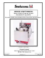
2. Remove the sensor cover by pressing firmly on each of the four removal
tabs that hold the cover in place.
3. Vacuum the screen carefully without removing it. If further cleaning is
required continue with Step 4, otherwise skip to Step 7.
4. Remove the chamber cover/screen assembly by pulling it straight out.
5. Use a vacuum cleaner or compressed air to remove dust and debris from
the sensing chamber.
6. Reinstall the chamber cover/screen assembly by sliding the edge over the
sensing chamber. Turn until it is firmly in place.
7. Replace the cover using the LEDs to align the cover and then gently push-
ing it until it locks into place.
8. Reinstall the detector.
9. Test the detector as described in TESTING.
10. Reconnect disabled circuits.
11. Notify the proper authorities that the system is back on line.
SPECIAL NOTE REGARDING SMOKE DETECTOR GUARDS
Smoke detectors are not to be used with detector guards unless the combina-
tion has been evaluated and found suitable for that purpose.
FIGURE 3: FEATURES OF THE PHOTO DETECTOR
Magnet
Test
Marker
LED
Base
Alignment
Notch
Magnet Test Marker
Base Alignment Notch
LED
Remote
Test
Capab
le
C2021-01
FIGURE 4: CLEANING THE PHOTO DETECTOR
Cover
Removal
Tabs
Sensor Cover
Sensing Chamber
Cover and Screen
Sensing Chamber
C2022-00
SPECIAL APPLICATION
When configured at the fire alarm control panel, this detector is capable of op-
erating in a special application mode such that it has a higher sensitivity than
is normally allowed by UL 268 for areas where early warning is important. In
this mode, the detector does not comply with the Cooking Nuisance Smoke
Test. Detectors (Sampling ports) set to the special application mode are not
suitable for use in areas where cooking appliances may be used. If cooking
appliances are used within the protected space, a normal application detector
or normal application mode must be used for that area.
Special application mode is not for general use and the detector may be more
prone to false alarms if used in unsuitable environments. While no list is
all-inclusive, some examples of unsuitable environments for special applica-
tion mode are areas with airborne particulate or aerosols including sawing,
drilling, and grinding operations, textile or agricultural processing, or areas
with engines that are not vented to the outside. A complete list of aerosol and
particulate sources is available in the Annex of NFPA 72.
Suitable environments for special application mode could include early warn-
ing for hospitals, museums, assisted living and other areas that do not have
airborne particulate or aerosols.
Refer to the fire alarm control panel documentation for information on how to
configure the detector for special application mode.
FCC STATEMENT
This device complies with part 15 of the FCC Rules. Operation is subject to the following two conditions: (1) This device may not cause harmful interference,
and (2) this device must accept any interference received, including interference that may cause undesired operation.
NOTE:
This equipment has been tested and found to comply with the limits for a Class B digital device, pursuant to Part 15 of the FCC Rules. These limits
are designed to provide reasonable protection against harmful interference in a residential installation. This equipment generates, uses and can radiate radio
frequency energy and, if not installed and used in accordance with the instructions, may cause harmful interference to radio communications. However, there
is no guarantee that interference will not occur in a particular installation. If this equipment does cause harmful interference to radio or television reception,
which can be determined by turning the equipment off and on, the user is encouraged to try to correct the interference by one or more of the following
measures:
– Reorient or relocate the receiving antenna.
– Increase the separation between the equipment and receiver.
– Connect the equipment into an outlet on a circuit different from that to which the receiver is connected.
– Consult the dealer or an experienced radio/TV technician for help.
This Class B digital apparatus complies with Canadian ICES-003.
Please refer to insert for the Limitations of Fire Alarm Systems
DEVICE AND SYSTEM SECURITY
Before installing this product ensure that the
tamper seal on the packaging is present and
unbroken and the product has not been tampered
with since leaving the factory. Do not install this
product if there are any indications of tampering.
If there are any signs of tampering the product
should be returned to the point of purchase.
It is the responsibility of the system owner to
ensure that all system components, i.e. devices,
panels, wiring etc., are adequately protected to
avoid tampering of the system that could result
in information disclosure, spoofing, and integrity
violation.
Preliminary 2 I56-6524-001
©2019 Fire-Lite. 09/23/2019