107111-11-EN FR26 GLO 503 Printed in Germany
5
EXTENSION MODULES AND EXTERNAL
CONTACTORS
One or more FF-SRE Extension Modules or external safety
contactors with positive guided safety contacts can be used
to multiply the number of contacts of the FF-SRM200P2
module.
IMPROPER EXTERNAL SAFETY CONTACTOR
MONITORING
•
The proper operation of external safety contactors or
FF-SRE extension modules must be monitored using
the External Device Monitoring (EDM function of the
FF-SRM200P2 muting module). The correct operation of
the external contactors is then checked when pushing
the start push-button.
•
Refer to the application warnings and application
examples for details.
Failure to comply with this instruction could result in
death or serious injury.
LED INDICATORS
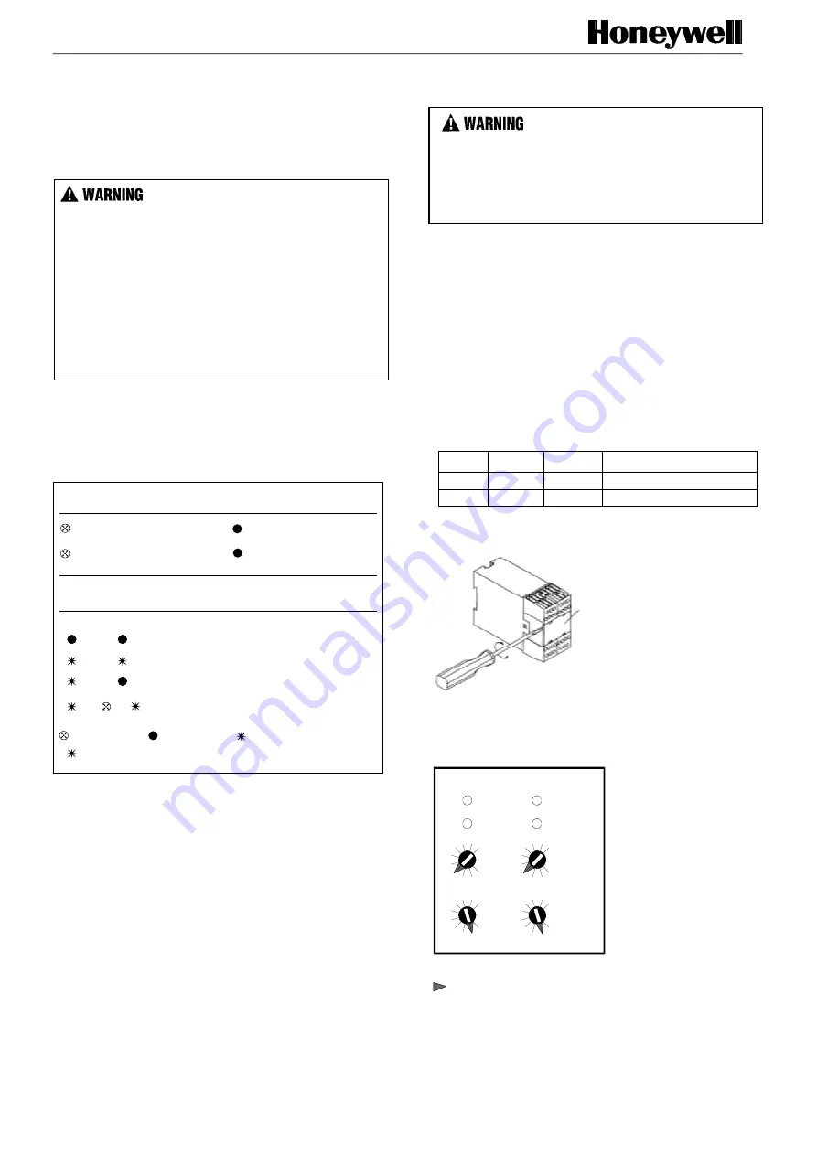
The FF-SRM200P2 module has 4 LED indicators: two
green LED relay status indicators (K1, K2) and two yellow
LED status indicator (Run 1, Run 2) on the front panel.
FIG 8. LED INDICATORS
Relay outputs status (K1, K2)
Internal relays are energized
NO contacts are closed
NC contact is open
Internal relays are de-energized
NO contacts are open
NC contact is closed
light off
n-times flashing (error)
light on
flashing (0,66 Hz)
Diagnostic information (Run 1, Run 2)
Run 1
Run 2
or n
n
n
Normal operating
Waiting for restart
Application error
n
Fatal error
MODE SETTING
ELECTRICAL SHOCK
Remove power from the FF-SR safety control modules and
the machine during installation and before setup. Ensure
that installation is performed by qualified personnel.
Failure to comply with these instructions could result
in death or serious injury.
The operating modes of the FF-SRM200P2 module are set
using 4 selectors located behind the removable front panel.
60 different programs are available allowing to select the
muting modes, the mutual exclusion modes, the max.
muting time, the test mode (safety devices with or without
test input) and the External Device Monitoring (EDM)
modes.
The FF-SRM200P2 module has two redundant
microprocessor channels. The mode setting of each channel
is done by two selectors "A" and "B".
The position of the corresponding selector "A" or "B" for
channel 1 and channel 2 must be identical (see example).
Example: Selecting mode “31”
Selector
Channel 1
Channel 2
Description
"A"
3
3
Muting with 2 auxiliary sensors
"B"
1
1
Maximum muting time: 20 s
FIG 7. FRONT PANEL REMOVAL
Panel
FIG 8. MODE SELECTOR “A” AND “B” FOR
CHANNEL 1 AND CHANNEL 2
Internal view
example "31"
channel 1
run1
K1
run2
K2
6
3
0
9
6
3
0
9
6
3
0
9
6
3
0
9
channel 2
Selector
"A"
Selector
"B"
F
S
RM
200_7
F
S
RM
200_8
F
S
RM
200_10


