43-TV-33-56 iss.4 GLO Aug 19 UK
9
Re-assembling the Unit
Remove or add any relevant plastic blanking plates (safety cover) on
the rear panel, by pushing out the push rivets from behind.
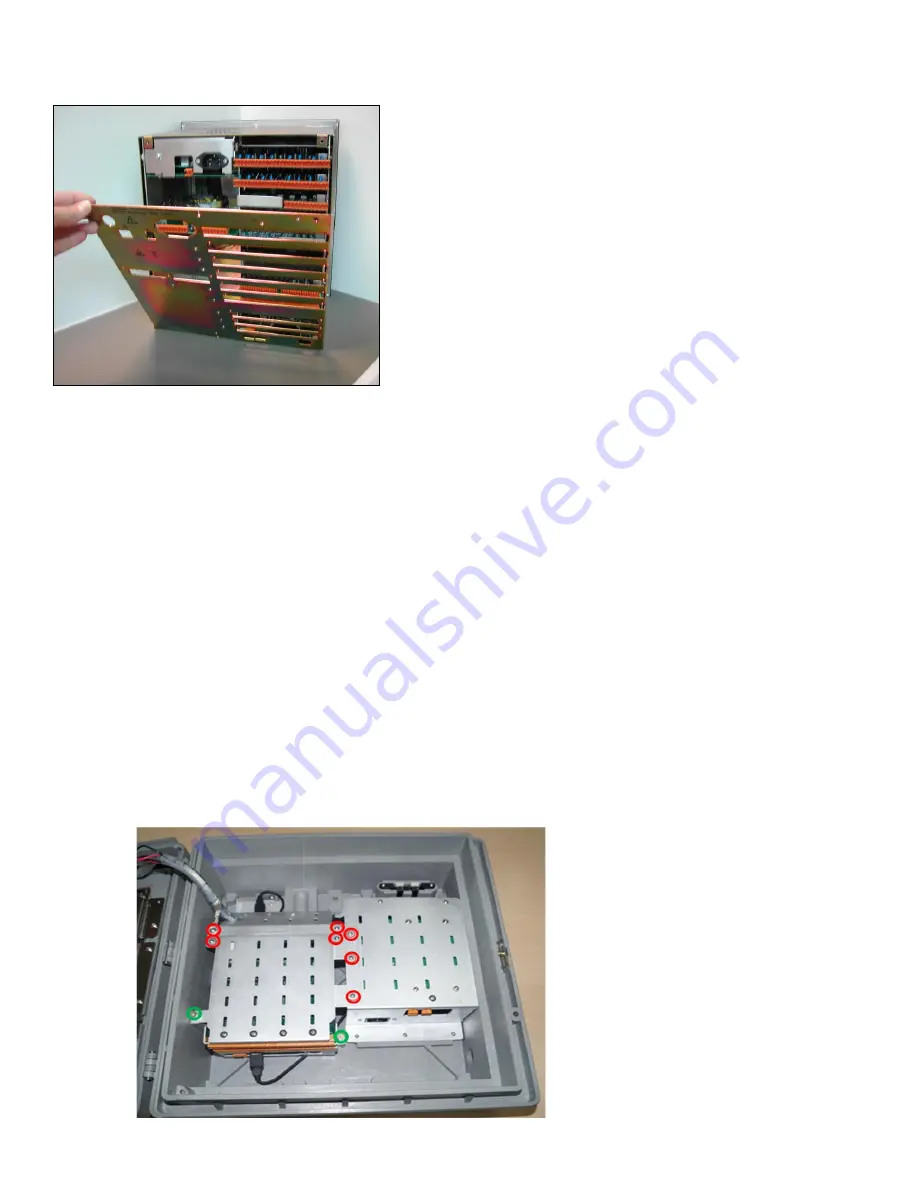
To replace the rear panel, angle the rear panel as shown to line up
two location points with the floor of the recorder’s case.
Reposition the shake-proof washers and replace and tighten two
screws (Minitrend and eZtrend = M3 x 6, Multitrend = M4 x 8) at the
top corners of the rear panel.
If the recorder has been removed from the panel, refit the mounting
clamps to the case in two opposite positions (Nema 4 positions) and
secure into the panel.
Minitrend and eZtrend torque setting should be 0.5 - 0.75Nm/4.4 -
6.6lbf-in
Multitrend torque setting should be 0.5 - 0.70Nm/4.4 - 6.2lbf-in
Once the recorder is re-assembled plug the CJC sensor supplied with the board into the centre two pins on the
connector. If the CJC is not connected thermocouple inputs will not operate.
DR Graphic Recorder
While adding a new piece of hardware to your recorder please be aware that if you are running Trend Manager PC
software,
the “Hardware Wizard” requires updation to accommodate the hardware changes.
Panel Mounting
IO cards can be removed, replaced or added to the recorder without removing it from its mounting panel. If you require
the recorder to be removed from the panel, loosen the mounting bracket screws and remove the recorder.
Removing the IO Card Chassis front panel
Removal of the IO Cards Chassis front panel is necessary for replacement or fitting any of the PC cards. To remove the
IO Card Chassis front panel, use following procedure.
1. Open the door (Bezel side) of the unit by unlocking the latch.
2. There are 7x No.4/40 screws as shown in red circle and 2x captive screws shown in green circle in Figure 17.
Remove all No.4/40 screws and loosen the captive screws.
Figure 16 - Multitrend recorder
Figure 17
Inside DR Graphic
Recorder Case


