


43-TV-33-56 iss.4 GLO Aug 19 UK
3
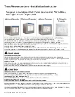
Minitrend Cards
Position Shown
Card Type
Slot
1
Power Supply Card
Transmitter Power Supply Card
2
Analogue Input Card
A, B
3
Pulse Input Card
A, B
Analogue Output Card
B (Not shown)
4
Alarm/Digital IO Card
G
5
Processor Card
Mother Board
Not shown
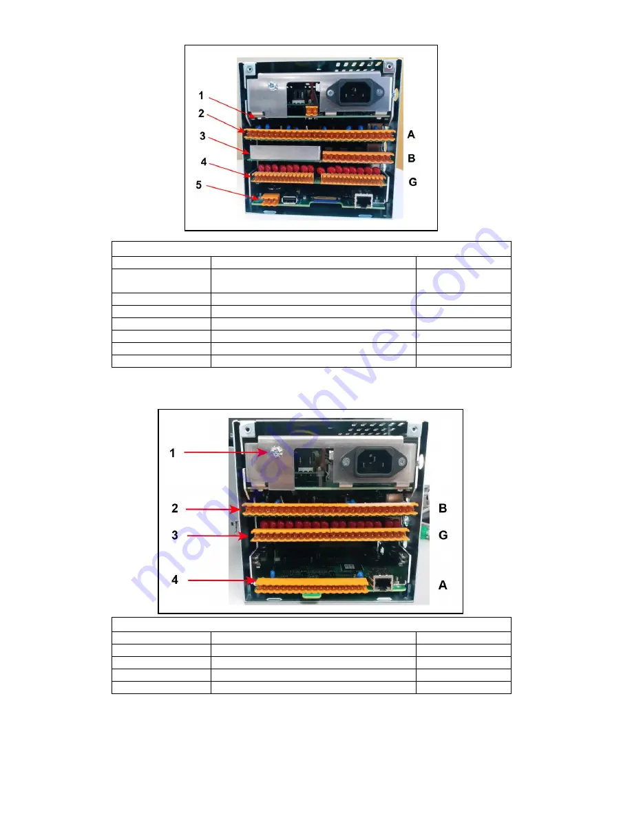
eZtrend cards
Position Shown
Card Type
Slot
1
Power Supply Card
2
Analogue Input Card
B
3
Alarm/Digital IO Card
G
4
Processor /AI Card
A
Figure 2 -
Minitrend recorder
Figure 3
eZtrend Recorder


