


5. PC CONFIGURATION
5-21
5.9 USER ACTUATION MENU
5.9.1 Edit User Actuation File
The User Actuation function allows you to define a new sensor range that does not exist in the recorder.
Each User Actuation is stored in a *.ua file separated from the configuration files for easy exporting.
Electrical measures can be matched with engineering units either by a set of segments or a set of
polynomials. Thus, you must create a table defining segments.
A User Actuation file (*.fua) defined with polynomials can be established so that the sensor actuation will
have the same accuracy as the recorder standard ranges.
To create a specific range of sensor:
1. Click on "User Actuation".
2. Click on "Edit User Actuation File" in the main menu to create a specific range of sensor.
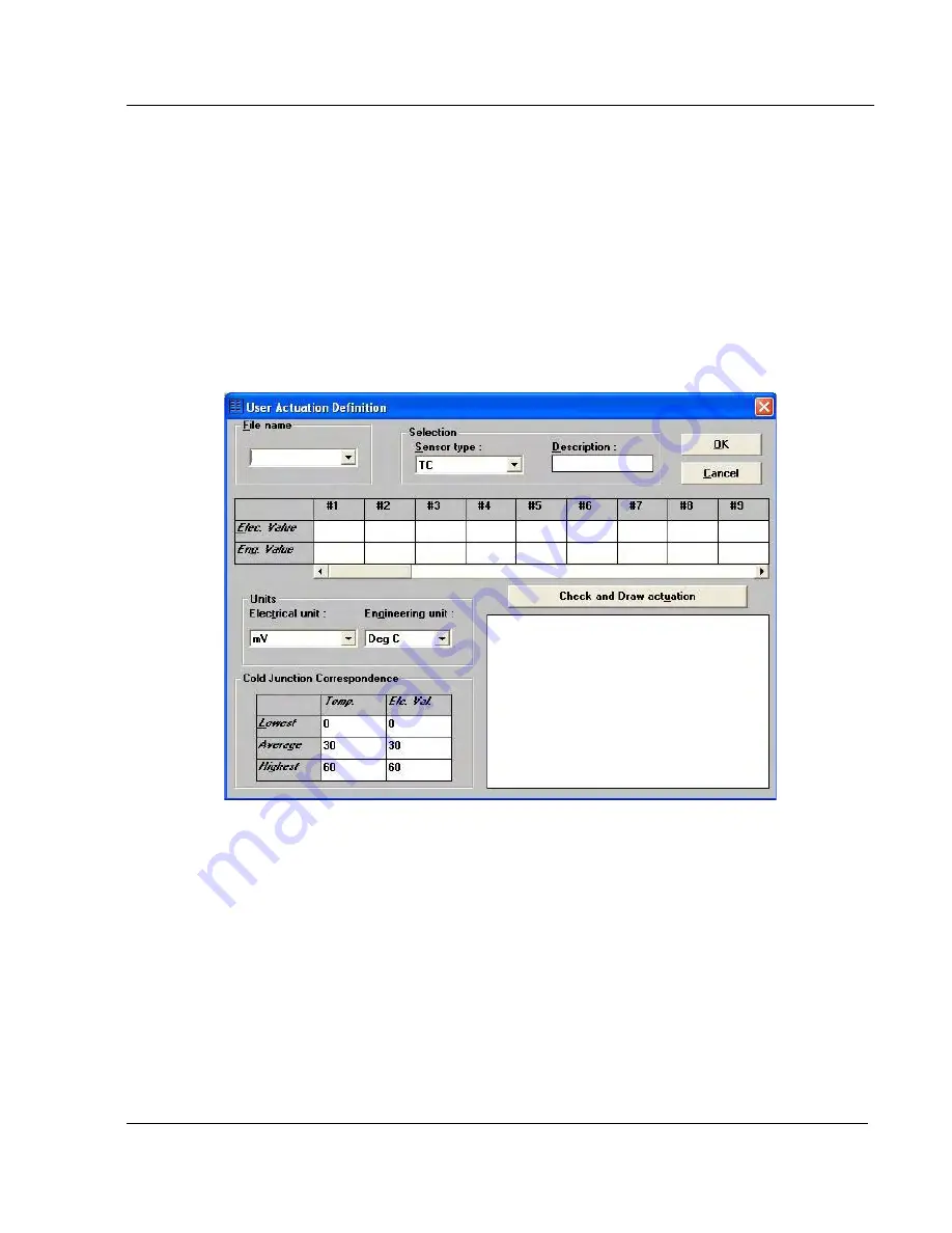
3. Enter the actuation file name in the “File name” field
4. The “Sensor type” may be TC, RTD or SPECIAL.
5. The Description textbox is the range name of the sensor that will be displayed by the recorder,
when reading the input range configuration.
6. The grid for electrical and engineering values represents the sensor actuation. Up to 50 pairs of
points can be entered.
-
Electric unit: mV, V, mA or Ohm
-
Engineering unit: - for TC or RTD sensor: Deg C or Deg F
-
for SPECIAL sensor: to be entered
7. The “Cold Junction Correspondence” grid is for TC sensors only.
8. Click on "Check and Draw actuation" to check if data have been correctly entered.
9. Click on "OK" to close and save the actuation file or click on "Cancel" to abort changes and keep
the previous data.
Summary of Contents for DPR180
Page 1: ...DPR180 PRODUCT MANUAL Issue 13 March 2010 US1I 6171 ...
Page 2: ......
Page 3: ...DPR 180 DIGITAL STRIP CHART RECORDER PRODUCT MANUAL Ref US1I 6171 Issue 13 March 2010 ...
Page 4: ......
Page 8: ......
Page 15: ...1 5 1 OVERVIEW ...
Page 16: ...1 6 1 OVERVIEW ...
Page 22: ...2 6 2 INSTALLATION ...
Page 24: ...2 8 2 INSTALLATION 2 5 TERMINAL CONNECTIONS ...
Page 31: ...2 15 2 INSTALLATION 2 6 FITTING THE CHART ...
Page 33: ...2 17 2 INSTALLATION ...
Page 34: ...2 18 2 INSTALLATION ...
Page 35: ...2 19 2 INSTALLATION ...
Page 39: ...2 23 2 INSTALLATION ...
Page 59: ...4 5 4 CONFIGURATION 4 3 PRINCIPLE OF CONFIGURATION ...
Page 60: ...4 6 4 CONFIGURATION ...
Page 74: ...4 20 4 CONFIGURATION ...
Page 85: ...4 31 4 CONFIGURATION ...
Page 89: ...4 35 4 CONFIGURATION ...
Page 98: ...4 44 4 CONFIGURATION NONE STD MESSAGE MESSAGE ON ...
Page 99: ...4 45 4 CONFIGURATION MESSAGE OFF MESSAGE ON OFF ...
Page 101: ...4 47 4 CONFIGURATION ...
Page 111: ...4 57 4 CONFIGURATION ...
Page 113: ...4 59 4 CONFIGURATION ...
Page 122: ...4 68 4 CONFIGURATION ...
Page 130: ...4 76 4 CONFIGURATION ...
Page 137: ...4 83 4 CONFIGURATION ...
Page 141: ...4 87 4 CONFIGURATION ...
Page 149: ...4 95 4 CONFIGURATION ...
Page 155: ...4 101 4 CONFIGURATION ...
Page 169: ...4 115 4 CONFIGURATION 4 6 CONFIGURABLE AND PRINTABLE CHARACTERS ...
Page 199: ...6 1 6 KITS LIST ...
Page 200: ...6 2 6 KITS LIST ...
Page 204: ...7 2 7 TROUBLESHOOTING 7 1 PARTS LOCATION ...
Page 205: ...7 3 7 TROUBLESHOOTING ...
Page 214: ...7 12 7 TROUBLESHOOTING ...
Page 236: ...8 22 8 SERVICE ...
Page 246: ...9 10 9 PRODUCT SPECIFICATION SHEET ...
Page 247: ...10 1 10 PROMPTS TRANSLATIONS TABLE OF CONTENTS Section Page 10 1 MATRICES 10 2 ...
Page 259: ...11 3 11 CONFIGURATION WORKSHEET 11 2 ANALOG INPUT ...
Page 260: ...11 4 11 CONFIGURATION WORKSHEET 11 3 CHART ...
Page 261: ...11 5 11 CONFIGURATION WORKSHEET ...
Page 262: ...11 6 11 CONFIGURATION WORKSHEET 11 4 ALARM ...
Page 263: ...11 7 11 CONFIGURATION WORKSHEET ...
Page 264: ...11 8 11 CONFIGURATION WORKSHEET 11 5 DIGITAL ...
Page 265: ...11 9 11 CONFIGURATION WORKSHEET ...
Page 266: ...11 10 11 CONFIGURATION WORKSHEET 11 6 MESSAGES ...
Page 267: ...11 11 11 CONFIGURATION WORKSHEET ...
Page 281: ...9 ...
Page 284: ...12 ...
Page 285: ......


