Honeywell DKG 972 Manual Download Page 4

4

INSTALLATION INSTRUCTIONS AND MAINTENANCE

1. Important notes

– The controls must be installed by qualified personnel

only. The relevant national regulations have to be
observed.

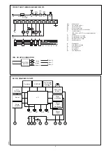
– On commissioning the wiring has to be carefully check-

ed according the appropriate diagram, Incorrect wiring
can damage the unit and endanger the installation.

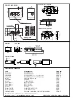
– The fuse rating has to ensure that the limits specified in

TECHNICAL DATA will not be exceeded. If these precau-
tions are not observed, the effect of a short circuit can
cause severe damage to the control and installation.

– For safety reasons a minimum of one control shutdown

every 24 hours has to be observed.

– Disconnect the mains before the control box is plugged

in or out.

– The control box is a safety device and must not be

opened!

2. Function control

For safety reasons the flame detection system should be
tested on commissioning the installation as well as after a
service or longer shut-down.

a) Attempt to start with gas valve closed:

– At the end of the safety interval

-> Lockout

b) After a normal start, with the burner in operation, close

the gas valve:
– After restart at the end of the safety interval

-> Lockout

DKG 972

3. Fault finding

The built-in information system facilitate the trouble shooting
in the case of problems occurring during start-up or during
operation.
A list of possible lock out messages can be found in
APPLICATION FEATURES chapter 1.2.

Please note:
The control box is locked in lock out mode
and the reasen for the lock out is displayed
until the control box is reset, either by an
internal or external reset (see also subject “3.
Lock out and reset").

Removing the control box from its wiring base or by
interrupting the supply line may not reset a lock out. Therefore,
by applying power, it needs 2-3 secs. before the control box
goes to lock out again and the cause of the last lock out.

Error

Possible fault

Burner not working

- Thermostat circuit open
- Faulty electrical wiring
- Mains voltage < 187 V (< 80 V)
- Terminal A continuously on
   power (e.g. terminal A is used as
   a support terminal)

After 2-3 secs. after applying - Control box has not been reseted
power. the unit goes to
lock out
Burner starts,

- stray light signal during waiting

flame not established,

time

lock out

- no ignition or no fuel

Burner starts,

- no or too low flame signal (min.

flame established,

valves see TECHNICAL DATA)

after safety time,

- wrongly wired, phase and neutral

lock out

reversed

- Ionisation probe dirty, broken or

has contact to frame ground

- too little light on flame sensIor

(IRD)

Summary of Contents for DKG 972

Page 1: ...iring ThewiringbaseS98isequippedwithspare andextraterminals andallowstogetherwith avarietyofcableentrypointsutmost flexibility of electrical wiring The DKG 972 are compatible with the TFI 812 Differentareonlythepre andpost ignitiontimes Max heatingpoweraccordingthelimitsintheGasAppliance Directive TECHNICAL DATA Operating voltage 220 240 V 15 10 50 Hz 5 or 110 120 V 15 10 60 Hz 5 Fuse rating 10 A ...

Page 2: ...ings APPLICATION FEATURES 1 Information system The information system is microprocessor based and re ports on all aspects of burner control box operation and flame supervision It informs continuously about the actual programming sequence the unit is just performing Besides monitoring of the programming sequence it also allows to identify errors during start up of operation without any additional t...

Page 3: ...the voltage drops below 160 Veff 80 Veff during start up or run time the control box proceed to safety shut down and goes into a waiting status If the voltage rises again the control box performs automatically a start up as soon as the mains voltage is 187 Veff 94 Veff 5 Safety The design and control sequence of the DKG 972 controls will comply with the currently applicable standards and regulatio...

Page 4: ...l Lockout DKG 972 3 Fault finding Thebuilt ininformationsystemfacilitatethetroubleshooting in the case of problems occurring during start up or during operation A list of possible lock out messages can be found in APPLICATION FEATURES chapter 1 2 Please note The control box is locked in lock out mode and the reasen for the lock out is displayed until the control box is reset either by an internal ...

Page 5: ...RS Fault display Information system EEPROM Oscillator tw tf tvz tn ts tv2 HS Mains switch GW Gas proving switch ST Limit thermostat RT Control thermostat EV External reset and lock out button IS Ionisation probe IRD 1020 1 UVD 971see separate diagram Z Ignition V1 Solenoid valve 1st stage V2 Solenoid valve 2nd stage SA External lock out signal M Auxiliary blower tw Waiting time tf Stray light moni...

Page 6: ...1 end on 16532 Flame detector IRD 1020 1 left 16533 Flame detector IRD 1020 1 right 16531 optional UVD 971 16722 Support for IRD Holder M93 for IRD 1020 59093 Support for UVD Holder M74 for UVD 59074 Connection cable Plug type 3 core cable 0 6 m with tag wire ends 7236001 The above ordering information refers to the standard version Special versions are also included in our product range Specifica...

Page 7: ... RG12 1EB SLOVAKIA UNITED KINGDOM Phone 421 2 58247 400 Switchboard 44 0 1344 656000 Fax 421 2 58247 415 Information Centre Tel 44 0 1344 656235 Information Centre Fax 44 0 1344 656240 e mail info slovakia honeywell com Email Uk infocentre honeywell com internet www honeywelluk com Germany Austria Switzerland Benelux Honeywell GmbH Honeywell B V Kaiserleistrasse 39 Laarderhoogtweg 18 63067 Offenba...

Reviews: