


This function will be used largely to report controller status information, and so a bit
set to 1 indicates that the corresponding feature is currently enabled/active, and a
bit reset to 0 indicates the opposite.
If an exact multiple of eight bits is not requested, the data is padded with trailing
zeros to preserve the 8-bit format. After the data has been transmitted, the CRC16
value is sent.
B.
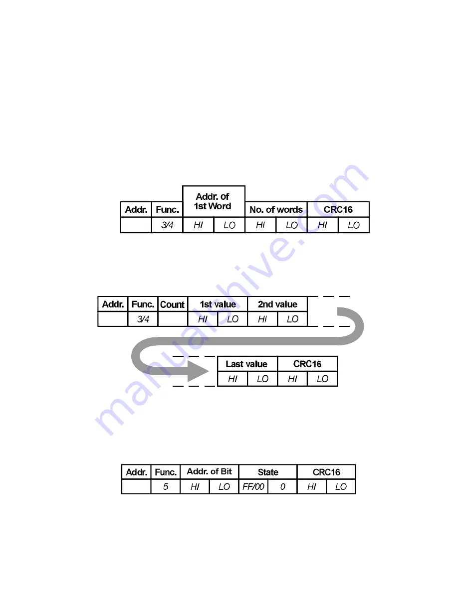
Read Holding Registers
(Read n Words)
03/04
The message sent to the controller to obtain the value of one or more registers is an
eight-byte message as follows:
The reply sent by the controller echoes the first 2 characters received and then
contains a single-byte data byte count, the value of which does not include either
itself or the CRC value to be sent. For this message, the count equals the number of
parameters read times two. Following the byte count, that number of parameter
values are transmitted, MSB first, followed by the CRC16.
C.
Force Single Coil
(Write 1 Bit)
05
B
The message received by the controller is 8 bytes long, consisting of the standard
preamble and the address of the bit to force, followed by a two-byte word whose
MSB contains the desired truth value of the bit expressed as 0xFF (TRUE) or 0x00
(FALSE).
Generally, this function will be used to control such features as Auto/Manual and
Tuning. The normal reply sent by the controller will be a byte-for-byte echo of the
message received.
5-3
Summary of Contents for DCP 50
Page 1: ...Sensing and Control DCP 50 Digital Controller Programmer Product Manual 57 77 25 17 3 00 ...
Page 4: ......
Page 8: ...1 BASE MODE 1 1 DISPLAY SEQUENCE NO PROGRAM RUNNING 1 1 ...
Page 17: ...2 3 Figure 2 4 Rear Terminal Connections ...
Page 23: ...3 2 2 Defining Segments Rate Mode 3 3 ...
Page 24: ...3 2 3 Defining Segments Time Mode 3 4 ...
Page 25: ...3 2 4 Program Options 3 5 ...
Page 35: ...4 6 Figure 4 1 Proportional Band and Overlap Deadband ...
Page 36: ...4 7 Figure 4 2 Alarm Operation ...
Page 37: ...4 8 Figure 4 3 Alarm Hysteresis Operation ...
Page 51: ...6 2 Figure 6 2 Hardware Definition Code Access and Adjustment ...
Page 60: ...7 2 Figure 7 2 Removing the Output 2 Output 3 Option PCBs ...
Page 87: ......
Page 88: ......
Page 89: ......
Page 90: ......
Page 91: ......
Page 92: ......
Page 93: ......
Page 94: ......
Page 95: ......
Page 96: ......
Page 97: ......


