background image

HAWK 8000 CONTROLLER – INSTALLATION & COMMISSIONING INSTRUCTIONS 

EN1Z-1016GE51 R0218 

A-

A+

S

END

BIA

MID

END

BIA

MID

47.5 kOHM

47.5 kOHM

+5V

ISO

GND-A

END

BIA

MID


Fig. 13. RS485-A 3-position bias switch set to MID 

 
The recommended bias switch setting depends upon the 
location and usage of the given HAWK 8000. It also depends 
upon the selected communication protocol (BACnet MS/TP, 
Panel Bus, or Modbus RTU Master communication, 
respectively). 

NOTE:

  All terminals are protected (up to 24 Vac) against 

short-circuiting and incorrect wiring – except when 
the 3-position bias switch is set to "END," in which 
case the terminals of the RS485 bus have no such 
protection. Higher voltages may damage the device. 

NOTE:

  According to BACnet standards, a min. of one and a 

max. of two BACnet devices must have its/their bias 
resistors switched ON. In the case of the RS485 
ports of the HAWK 8000, setting the bias switch to 
either "BIAS" or "END" fulfills this requirement. 


RS485 Standard 

According to the RS485 standard (TIA/EIA-485: "Electrical 
Characteristics of Generators and Receivers for Use in 
Balanced Digital Multipoint Systems"), only one driver com-
municating via an RS485 port may transmit data at a time. 
Further, according to U.L. requirements, each RS485 port 
may be loaded with a max. of 32 unit loads. E.g., CentraLine 
devices have as little as ¼ unit load each, so that up to 128 
devices can be connected. 
BACnet MS/TP connections to the RS485 ports must comply 
with the aforementioned RS485 standard. Thus, it is re-
commended that each end of every connection be equipped 
with one termination resistor having a resistance equal to the 
cable impedance (120 Ω / 0.25 – 0.5 W). 
RS485 systems frequently lack a separate signal ground wire. 
However, the laws of physics still require that a solid ground 
connection be provided for in order to ensure error-free 
communication between drivers and receivers – unless all of 
the devices are electrically isolated and no earth grounding 
exists. 
 

IMPORTANT 

In the case of new HAWK 8000 controller installations, 
we strongly recommend using a separate signal 
ground wire. Doing otherwise may possibly lead to 
unpredictable behavior if other electrically non-isolated 
devices are connected and the potential difference is 
too high. 
In the case of the installation of HAWK 8000 con-

trollers in already-existent RS485 two-wire systems 
(e.g., when replacing PANTHER or LION controllers 
with HAWK 8000 controllers), not using a separate 
signal ground wire will probably have no undesirable 
effects. 

 
The cable length affects the baud rate. The following table 
provides a few examples. 

Table 2. Baud rate vs. max. cable length for RS485 

Baud rate 

Max. cable length (L) 

9.6 - 76.8 kbps 

1200 m 

115.2 kbps 

1000 m 

 
For information on wire gauge, max. permissible cable length, 
possible shielding and grounding requirements, and the max. 
number of devices which can be connected to a bus, refer to 
standard EIA-485. 
 

Ethernet Wiring 

The HAWK 8000 is equipped with two RJ45 10/100-Mbit 
Ethernet ports (see Fig. 8). They are labelled PRI (LAN1) for 
primary and SEC (LAN2) for secondary. Each port is capable 
of up to 100 mbits/sec baud, and uses a standard Ethernet 
patch cable for connection to an Ethernet switch. 
 

  WARNING 

Risk of electric shock or equipment damage!


► 

It is prohibited to connect any of the RJ45 sockets of the 
HAWK 8000 Controller to a so-called PoE-enabled device 
("

P

ower 

o

ver 

E

thernet"). 

 
The factory default IP address for PRI is 192.168.1.140. The 
subnet mask is 255.255.255.0. By default, SEC (LAN2) is 
disabled. 
Please see HAWK 8000 – Installation & Startup Guide 
(EN1Z-1027GE51) for details on the software configuration of 
the Ethernet ports. 

NOTE:

  Unless you have a specific application for SEC 

(LAN2) – e.g., when using it to isolate a driver's net-
work traffic – generally only PRI (LAN1) is used. 
If you wish to enable SEC, note that PRI and SEC 
must be connected to different IP subnets. Further, 
HAWK 8000 does not provide IP routing or bridging 
operation between two Ethernet ports. 


Power Up and Initial Checkout 

Apply power by inserting the 2-position 24V power connector 
plug. See also Fig. 7. 
Check the STAT (status) and BEAT (heartbeat) LEDs (Fig. 
14). 
When power is applied, the green STAT LED will light. This 
indicates that the system is OK, with power applied. During 
bootup, the BEAT LED may flash at 1 Hz with a 90% ON, 
10% OFF duty cycle. When bootup completes, the platform 
daemon is started, and the normal 1 Hz flash (50% ON, 50% 
OFF) duty cycle of the BEAT LED returns. 

Summary of Contents for Centra Line CLNXHAW-5K

Page 1: ...uded in Shipment 2 Overview of Features 3 Materials and Tools Required 4 Preparation 4 Mounting 4 Environmental Requirements 4 Dimensions Tab Mounting 4 Mounting on a DIN Rail 5 Wiring 5 Bus and Port Connections 6 Order Numbers 11 Drivers 11 Included Drivers 11 Optional Drivers 11 Specifications 12 Power 12 Environmental Specifications 12 Approvals Certifications etc 12 Related Technical Literatur...

Page 2: ...ety are invalidated Rules regarding electrostatic discharge should be followed Use only accessory equipment which comes from or has been approved by Honeywell Construction The HAWK 8000 Controller is an independently mounted electronic control unit with fixed wiring Mounting Method The HAWK 8000 Controller is suitable for mounting as follows in cabinets in fuse boxes conforming with standard DIN43...

Page 3: ...DC 50 60HZ 24W MAX OPERATING TEMPERATURE 20C to 60C REQ USE OF CLASS 2 24VAC TRANSFORMER OR EQUIVALENT 12977 8 Fig 1 HAWK 8000 overview of features 1 Earth ground 6 PRI primary LAN1 10 100 Mbit Ethernet connection 2 Terminal block for 24 VAC DC power supply 7 SEC secondary LAN2 10 100 Mbit Ethernet connection 3 RS485 A port and bias termination switch 8 Access shutter for microSD card slide to ope...

Page 4: ...ecial system password stored in the controller base software If you swap in a card from a previously configured unit you must re enter this same password using a serial connection to the controller s Debug port WARNING Risk of electric shock or equipment damage Disconnect the power supply before removing or inserting the microSD flash memory card Failure to do so is likely to damage the equipment ...

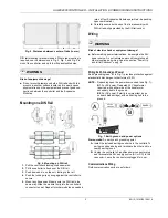
Page 5: ...ination 6 Carefully secure both ends of the final assembly with DIN rail end clips provided by the DIN rail vendor Wiring WARNING Risk of electric shock or equipment damage Before making power terminations de energize the 24V power source Do not restore power until completing all other mounting and wiring See also section Power Up and Initial Checkout on pg 8 Wiring Earth Ground and Power Earth gr...

Page 6: ...ition WiFi adapter is disabled ACC Left position Controller provides operation as a WiFi access point for up to 20 clients CLT Right position Controller operates as a client to an existing 802 11a b g n router or access point To use either screw in the antenna directly see Fig 9 or use an optional coax cable extension kit CBL WIFI EXT to locate the antenna up to 2 m away An associated LED remains ...

Page 7: ... baud and uses a 3 position screw terminal connector A A S RS485 A HAWK 8000 RS485 B DEVICE 1 DEVICE 1 DEVICE 2 DEVICE 2 DEVICE N DEVICE N B B S S S S S S S Fig 10 RS485 wiring example NOTE RS485 devices on the same network should use the same communication protocol and the same baud rate Up to 32 or more devices may be supported depending upon device specifications Use shielded twisted pair 18 22...

Page 8: ...predictable behavior if other electrically non isolated devices are connected and the potential difference is too high In the case of the installation of HAWK 8000 con trollers in already existent RS485 two wire systems e g when replacing PANTHER or LION controllers with HAWK 8000 controllers not using a separate signal ground wire will probably have no undesirable effects The cable length affects...

Page 9: ...at boot up also occurs during other critical operations such as a firmware upgrade to the controller and or any attached modules To be safe do not remove power from the controller while its BEAT LED is flashing in a 90 10 ON OFF duty cycle Instead wait for the normal 50 50 flash to return before removing power If the BEAT LED remains ON constantly does not light up or flashes very fast contact T A...

Page 10: ...s door opened Legend 1 BACKUP button and corresponding BACKUP LED 2 PROG USB 2 0 for use with USB flash thumb drive 3 DEBUG Micro A USB for serial debugging communications 4 SHT DWN Recessed pushbutton for initiating a controlled shutdown The DEBUG port is a standard Micro A type USB port for serial debugging communications to the controller You can use a serial terminal program for example PuTTY ...

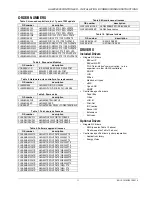
Page 11: ...5 HAWK8 PLUS 1250 POINTS UPGRADE CLNX DEVICE UP 50 HAWK8 PLUS 2500 POINTS UPGRADE Table 8 Software upgrade licenses OS number description CLNX SMA 8005 1YR HAWK8 1YR SW UPDATE 250 499 PTS CLNX SMA 8005 3YR HAWK8 3YR SW UPDATE 250 499 PTS CLNX SMA 8005 5YR HAWK8 5YR SW UPDATE 250 499 PTS CLNX SMA 8010 1YR HAWK8 1YR SW UPDATE 500 1249 PTS CLNX SMA 8010 3YR HAWK8 3YR SW UPDATE 500 1249 PTS CLNX SMA 8...

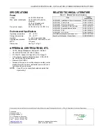
Page 12: ... MTTF 10 years Dimensions See Fig 3 to Fig 5 APPROVALS CERTIFICATIONS ETC UL 916 Energy Management Equipment Edition 4 CE 2014 53 EU RED 2011 65 EU RoHs FCC Part 15 Subpart B Class B Part 15 Subpart C C UL listed to Canadian Standards Assoc CSA C22 2 No 205 M1983 Signal Equipment Ethernet IEEEC 802 3 Purpose of the device is multifunctional non safety control intended for HVAC in home residential ...

Reviews: