


EAGLE CONTROLLER – INSTALLATION & COMMISSIONING INSTRUCTIONS
5
EN1Z-0970GE51
R1112
Bus and Port Connections
WARNING
Risk of electric shock or equipment damage!
►
Do not touch any live parts in the cabinet!
►
Disconnect the power supply before making connections
to or removing connections from terminals of the EAGLE
Controller or Panel Bus I/O modules.
►
Do not reconnect the power supply until you have
completed installation.
►
Observe the rules regarding electrostatic discharge.
BI
1
BI
2
BI3
BI4
GN
D
UI
1
UI
2
UI3
UI4
UI5
UI6
UI
7
24 25 26
27 28 29 30 31 32
33 34 35 36 37
38 39
40 41 42 43 44 45 46
UI
8
47
DO
1
DO
2
DO
3
IN
IN
4
DO
4
DO
5
IN5
IN6
DO
6
DO
7
IN7
IN
8
DO
8
GN
D
AO
1
AO
2
AO
3
5
6
7
8
9 10
11 12 13 14 15 16 17 18
19 20 21 22
24
V-
0
24V
~
1
AO
4
23
6
7
4
5
GND
1
48
5-
1+
48
5-
1-
n.a
.
n.a
.
GN
D2
48
5-
2+
48
5-
2-
n.a
.
UI
9
UI
1
0
!
L1 L2 Tx Rx
2
1
8
2
3
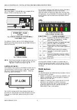
Fig. 2. Bus and port connections, LEDs (top view)
1
8
3
J1
J8
EN
D
BI
AS
MI
D
2
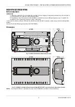
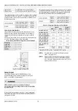
Fig. 3. Bus and port connections (side view)
Legend
1 RS232 / RJ45 socket (for factory debugging, only)
2 USB 2.0 Host Interface (for connection of external
communication interfaces, e.g., the IF-LON)
3 ETHERNET / RJ45 socket (CLEA2000Bxx and
CLEA2026Bxx, only)
4
RS485-1
(isolated)
5
RS485-2
(non-isolated)
6 LEDs (see also Fig. 9)
7 USB 2.0 Device Interface (for connection to CARE /
XW-Online)
8 Slide switch (for setting bias and termination
resistance of RS485-1)
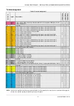
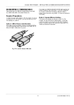
USB 2.0 Host Interface
Via its USB 2.0 Host interface, the EAGLE Controller can be
connected to, e.g., the IF-LON External Interface Adapter and
thus to L
ON
W
ORKS
networks. See also IF-LON External
Interface Adapter – Mounting Instructions (EN1Z-0974GE51).
USB 2.0
Host Interface
J1
J8
EN
D
BI
AS
MI
D
Fig. 4. USB 2.0 Host interface
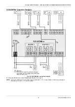
USB 2.0 Device Interface
All models of the EAGLE Controller are equipped with a USB
2.0 Device Interface at the front.
BI1
BI2
BI
3
BI
4
GND
UI1
UI2
UI
3
UI
4
UI5
UI6
UI
7
32
33 34 35 36 37
38 39
40 41 42 43 44 45 46
UI
8
47
n.
a.
UI9
UI10
USB 2.0
Device Interface
Fig. 5. USB 2.0 Device Interface
A standard USB type-B connector can be inserted into this
USB 2.0 Device Interface. This USB 2.0 Device Interface is
the recommended interface for connection to CARE.